
Automotive body and trim assembly with complementary locating and positioning features and method of assembling same

a technology of automotive body and trim assembly, which is applied in the direction of roofs, transportation and packaging, vehicle arrangements, etc., can solve the problems of affecting the final position of the body component, and achieve the effect of minimizing the variability of the final assembled position

Inactive Publication Date: 2010-03-30
GM GLOBAL TECH OPERATIONS LLC
View PDF8 Cites 9 Cited by
  • Summary
  • Abstract
  • Description
  • Claims
  • Application Information

AI Technical Summary

Benefits of technology

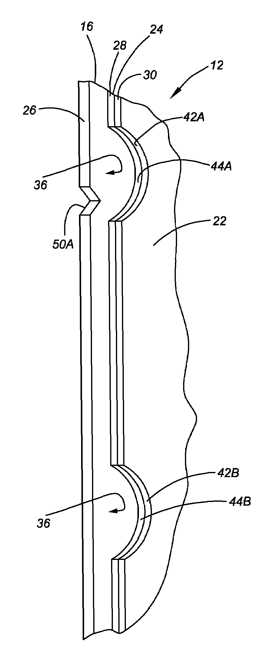
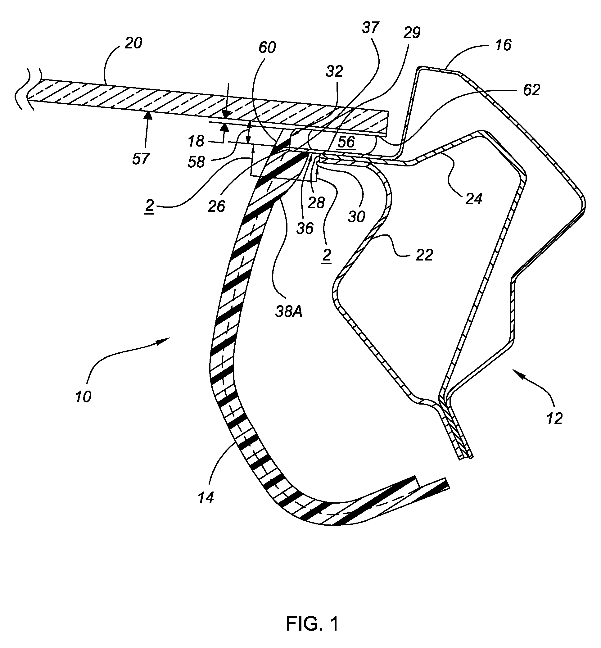
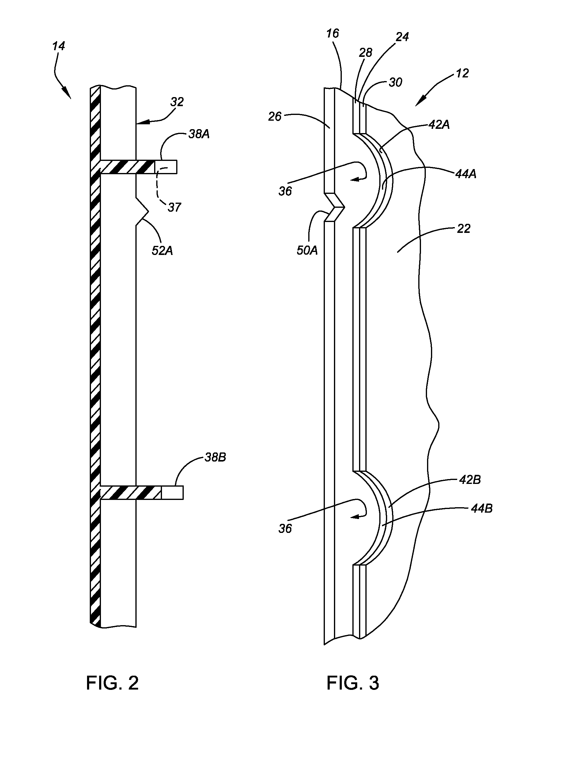
The present invention provides an automotive body and trim assembly that uses locating features on a single sheet metal layer of a multi-layer body frame pillar to fine-tune and minimize variability in the final assembled position of the trim member. The single sheet metal layer has both a fore-aft-locating feature and a cross-car-locating feature that act as secondary locating features to supplement the primary locating features of the body frame pillar. This ensures that the final assembled position of the trim member is accurate and minimizes any variations in position. The invention is not limited to an A-pillar and an A-pillar trim member. The method of assembly involves exposing the longitudinal edge and surface of a single sheet metal layer of the body frame pillar to establish the cross-car and fore-aft-locating features, and then contacting the body frame pillar with the pillar trim member to determine its final position.

Problems solved by technology

Additionally, aesthetic qualities often require minimization of positioning error.
Even when locating features are provided on the body component to aid in proper positioning of the trim member, the final position may be impacted by variability in the body component.

Method used


Image

  • Automotive body and trim assembly with complementary locating and positioning features and method of assembling same
  • Automotive body and trim assembly with complementary locating and positioning features and method of assembling same
  • Automotive body and trim assembly with complementary locating and positioning features and method of assembling same

Examples


Embodiment Construction

[0013]Referring to the drawings, wherein like reference numbers refer to like components, FIG. 1 shows an automotive body and trim assembly 10 with an A-pillar 12 and an A-pillar trim member 14 connected thereto. The automotive body and trim assembly 10 has attachment areas with primary locating features and attachment features (e.g., fasteners, not shown) that are received in the primary locating features to secure the A-pillar trim member to the A-pillar 12, as is known. As described below, the automotive body and trim assembly 10 is provided with supplemental locating features and positioning features that work in conjunction with the primary locating features to fine tune, i.e., more precisely control, the final assembled position of the A-pillar trim member 14. The locating features and positioning features described below are these supplemental features.

[0014]The A-pillar 12 has multiple sheet metal layers; however, locating features are included on only one of the sheet metal...


PUM


Abstract

An automotive body and trim assembly is provided that utilizes locating features on only a single sheet metal layer of a multi-layer body frame pillar to position a trim member, thus minimizing variability in the final assembled position of the trim member. The single sheet metal layer has both a fore-aft-locating feature and a cross-car-locating feature. A fore-aft-positioning feature and a cross-car-positioning feature on the pillar trim member are spaced to permit contact with the fore-aft-locating feature and the cross-car-locating feature, respectively when the pillar trim member is assembled with the body frame pillar, so that only the single sheet metal layer determines the fore-aft and cross-car position of the pillar trim member. A method of assembling a pillar trim member and a body frame pillar having multiple sheet metal layers is also provided.

Description

TECHNICAL FIELD[0001]The invention relates to an automotive body and trim assembly that includes a body frame pillar having locating features and a pillar trim member having positioning features positionable at the locating features for controlling the assembled position of the pillar trim member.BACKGROUND OF THE INVENTION[0002]Automotive manufacturers strive for assembly processes and component designs that enable repeatable and reliable positioning of vehicle components. The ability to achieve desired assembly configurations enhances consumer perception of quality. Additionally, aesthetic qualities often require minimization of positioning error. For example, the final assembled position of a body trim member depends in part upon its positioning on the body component to which it is to be attached. Even when locating features are provided on the body component to aid in proper positioning of the trim member, the final position may be impacted by variability in the body component. ...

Claims


Application Information

Patent Timeline
Patent Type & Authority Patents(United States)
IPC IPC(8): B60R13/02
CPCB60R13/0206B60R13/025B62D25/04B60R2013/0293
Inventor MARKS, STEPHEN W.BALGAARD, STEVEN P.BHATIA, HIRDE N.ENYEDY, VICTORIA L.WILSON, WAYNE S.BOUGHTON, CHARLES S.
Owner GM GLOBAL TECH OPERATIONS LLC
Learn More