
Method and device for dispensing sealant and LCD panel

a liquid crystal display and sealant technology, applied in liquid transferring devices, liquid handling, instruments, etc., can solve the problems of reducing curing time, affecting the adhesion strength, and contaminating the relationship between liquid crystal materials and sealants

Active Publication Date: 2012-07-17
BEIJING BOE OPTOELECTRONCIS TECH CO LTD +1
View PDF9 Cites 3 Cited by
  • Summary
  • Abstract
  • Description
  • Claims
  • Application Information

AI Technical Summary

Benefits of technology

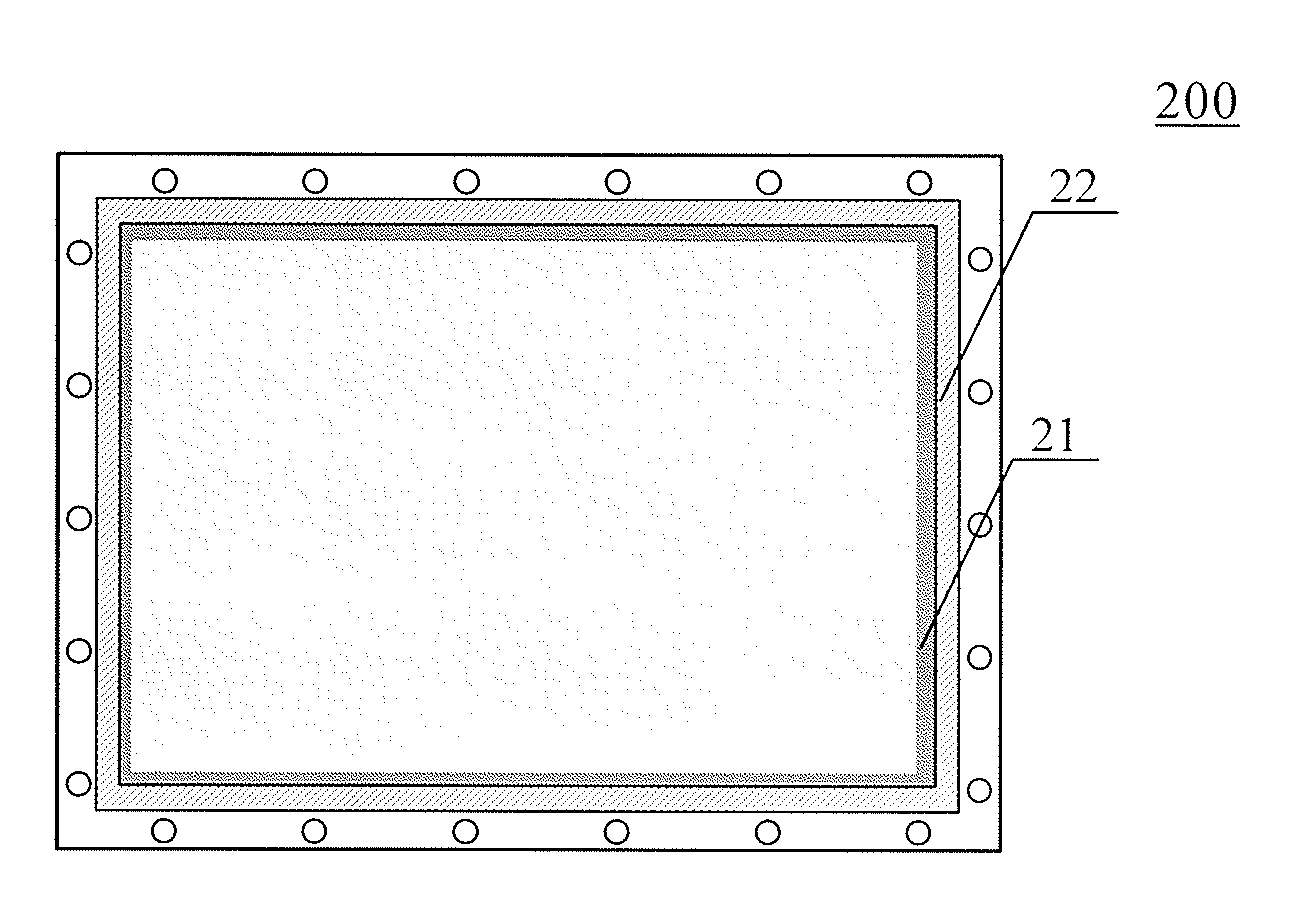
The present invention provides a method for dispensing sealant and a liquid crystal display device that uses the sealant. The method involves preparing an inner-side sealant and an outer-side sealant, and simultaneously dispensing them onto a substrate along four edges of the substrate. The inner-side sealant is a light curing sealant or a mixture of a light curing sealant and a thermal curing sealant, while the outer-side sealant is a thermal curing sealant or a mixture of a light curing sealant and a thermal curing sealant. The device for dispensing sealant includes a dispenser head with channels for holding the inner-side and outer-side sealants. The technical effects of the invention include improved sealing efficiency and reduced likelihood of sealant leakage.

Problems solved by technology

In this case, longer curing time is necessary when thermal curing sealant is used, and lower adhesion strength is exhibited when light curing sealant is used although the curing time is reduced.
The liquid crystal materials and the sealant may contaminate each other even when a mixture sealant is used.
In addition, when sealant that is not completely cured contacts with the liquid crystal materials, a chemical reaction may occur therebetween, and thus impurities may be introduced, in which case problems of bright pixel, light leakage, image sticking and the like may occur due to the impurities when the LCD panel is used to display an image.

Method used


Image

  • Method and device for dispensing sealant and LCD panel
  • Method and device for dispensing sealant and LCD panel
  • Method and device for dispensing sealant and LCD panel

Examples


Embodiment Construction

[0021]Embodiments of the present invention will be described hereinafter in detail with reference to the accompanying drawings.

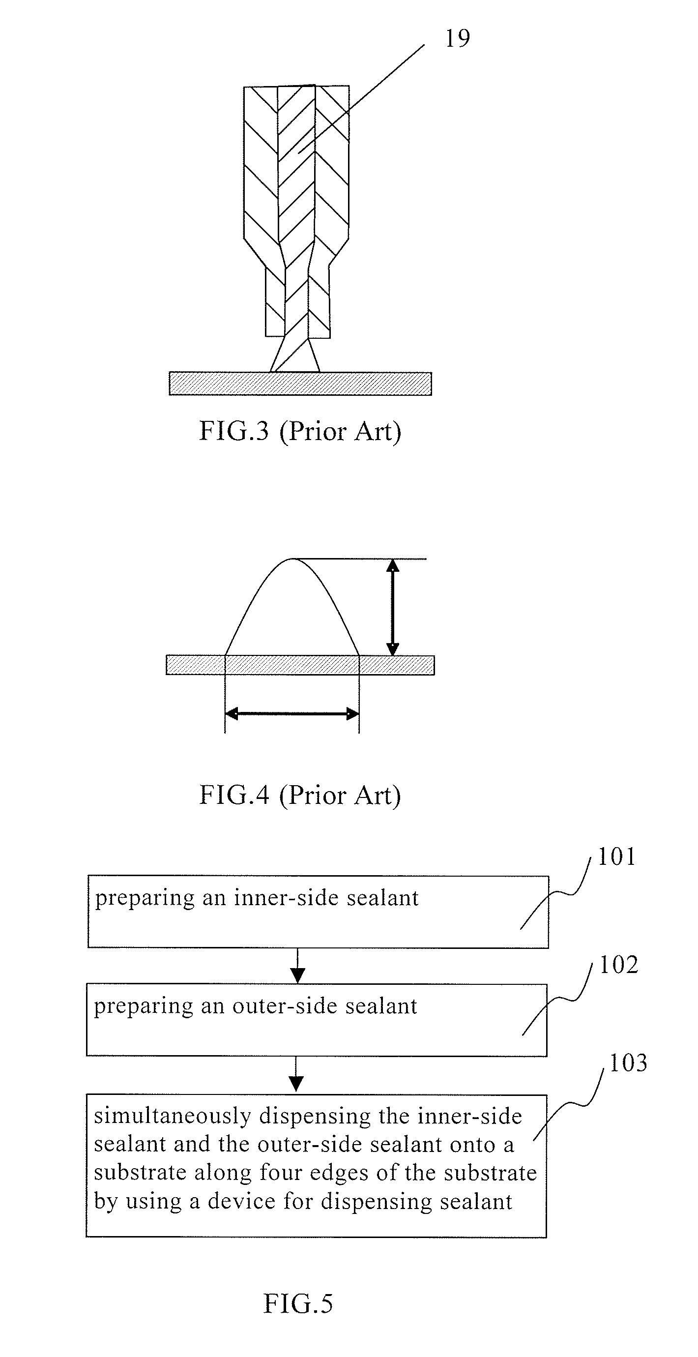
[0022]FIG. 5 is a flow chart showing an embodiment of a method for dispensing sealant according to the present invention, and as shown in FIG. 5, the method for dispensing the sealant according to the embodiment of the present invention comprises the following steps:[0023]step 101 of preparing an inner-side sealant;[0024]step 102 of preparing an outer-side sealant; and[0025]step 103 of simultaneously dispensing the inner-side sealant and the outer-side sealant onto a substrate along four edges of the substrate by using a device for dispensing sealant so that one side of the inner-side sealant abuts the sealed liquid crystal materials and the other side thereof integrates with the outer-side sealant.

[0026]In the conventional technology, only a homogeneous sealant configuration with uniform composition is formed when a thermal curing sealant or a light curing ...


PUM

PropertyMeasurementUnit
widthaaaaaaaaaa
inner diameteraaaaaaaaaa

Abstract

The method for dispensing sealant comprises: preparing an inner-side sealant that comprises a light curing sealant or a first mixture of a light curing sealant and a thermal curing sealant in which the content of the light curing sealant is more than that of the thermal curing sealant; preparing an outer-side sealant that comprises a thermal curing sealant or a second mixture of a light curing sealant and a thermal curing sealant in which the composition of the light curing sealant is less than or equal to that of the thermal curing sealant; simultaneously dispensing the inner-side sealant and the outer-side sealant onto a substrate along four edges of the substrate by using a device for dispensing sealant so that one side of the inner-side sealant abuts the sealed liquid crystal materials and the other side thereof integrates with the outer-side sealant.

Description

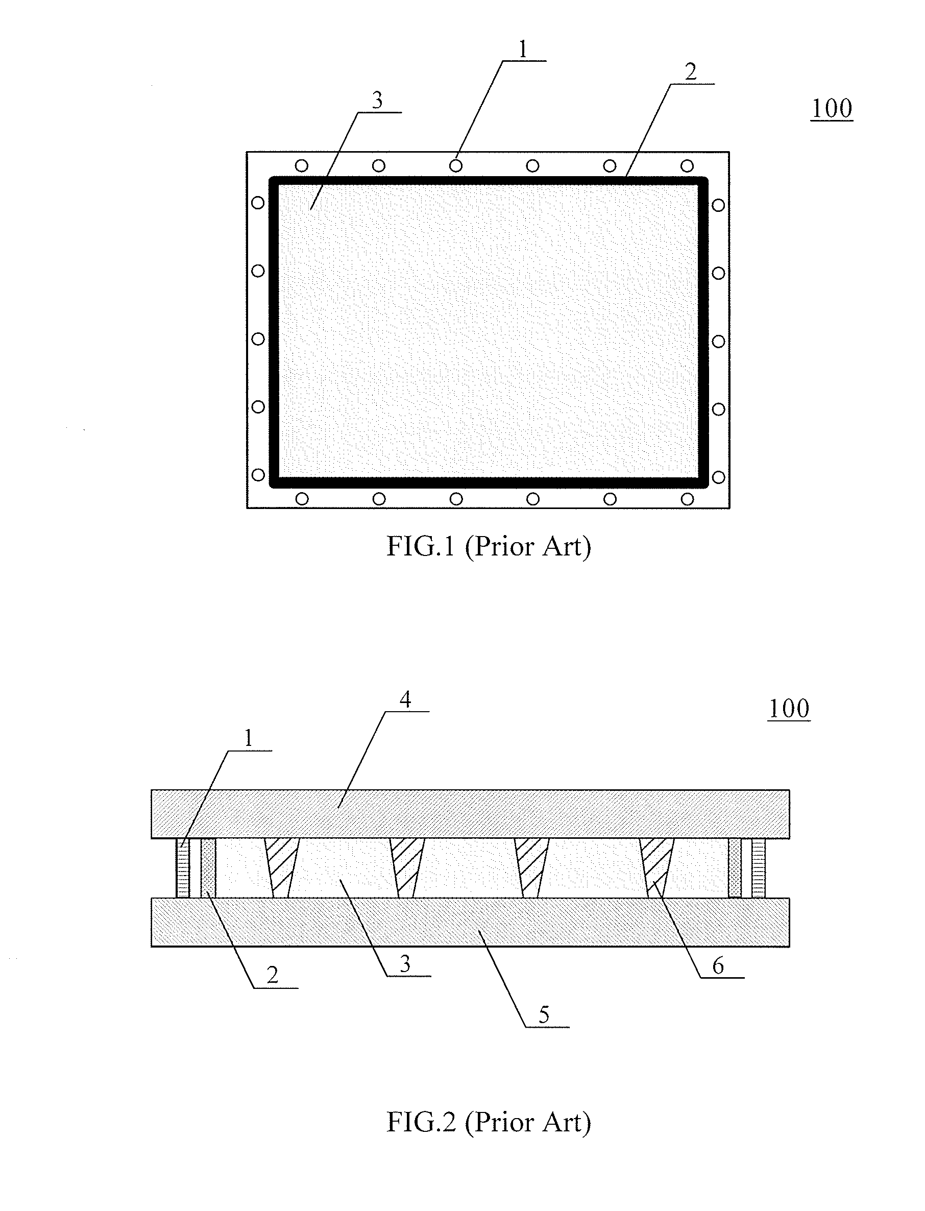
BACKGROUND[0001]Embodiments of the present invention relate to a method and a device for dispensing sealant and a liquid crystal display (LCD) panel.[0002]Recently, liquid crystal displays (LCDs) have being replacing cathode ray tube (CRT) displays and prevailing in the market of displays for televisions, computers and the like due to the characteristics of small volume, occupying relatively small space, etc. A LCD panel is formed by attaching an array substrate to a color filter substrate with a space therebetween and liquid crystal materials are disposed within the space. Generally, when the array substrate is attached to the color filter substrate, sealant is used to maintain the airproof state of the space between the array substrate and the color filter substrate and enclose liquid crystal materials within the space between the array substrate and the color filter substrate without exposing to exterior environment, and thus the cell gap between the substrates can be maintained ...

Claims


Application Information

Patent Timeline
Patent Type & Authority Patents(United States)
IPC IPC(8): G02F1/1339B67D7/78B67B7/00
CPCG02F1/1339G02F1/13
Inventor ZHAO, HAIYULIANG, JINGJING
Owner BEIJING BOE OPTOELECTRONCIS TECH CO LTD
Learn More