
System and method for automatically controlling deck plate position on a corn header

a technology of automatic control and corn header, which is applied in the field of system and method for automatically controlling the position of the corn header, can solve the problems of corn ears that may also tend to get pulled down, less support of the stalk, and broken stalks, so as to reduce the force, reduce or eliminate gaps or spaces, and reduce kernel loss

Active Publication Date: 2012-07-17
BLUE LEAF I P INC
View PDF16 Cites 41 Cited by
  • Summary
  • Abstract
  • Description
  • Claims
  • Application Information

AI Technical Summary

Benefits of technology

This solution enables precise control of deck plate positioning and pinching force, reducing stalk breakage, kernel loss, and trash accumulation by automatically adjusting channel width and force to maintain optimal conditions during corn harvesting, enhancing stalk throughput and reducing operational challenges.

Problems solved by technology

But, a disadvantage is that the upper ends of the stalks are less supported, and may tend to whip around more as the lower ends are collapsed into the ground, raising the potential that some stalks will be broken and ears will be lost.
Corn ears may also tend to get pulled down between the edges of the deck plates such that kernels are detached and lost.
Smaller ears may also get caught between the opposing deck plates and cause trash buildup.
In the second instance, if the pinch force is too great, stalks may get caught between the deck plates and bunch up in the channel and be damaged or broken such that, again, ears are lost, and more trash may be retained and carried by the gathering chains into the header.
However, if the operator lacks experience, or is inattentive, the channel width can be too big or small, resulting in the above listed problems.
As another problem, sugars from the stalks and dust adhered thereby to the plates and surrounding structure so as to reduce and even overcome the spring forces and inhibit free lateral adjusting movements of the plates, such that they can stick open too widely or too narrowly so as to undesirably affect the pinching force, disrupt stalk flow and ear removal, and the like.

Method used


Image

  • System and method for automatically controlling deck plate position on a corn header
  • System and method for automatically controlling deck plate position on a corn header
  • System and method for automatically controlling deck plate position on a corn header

Examples


Embodiment Construction

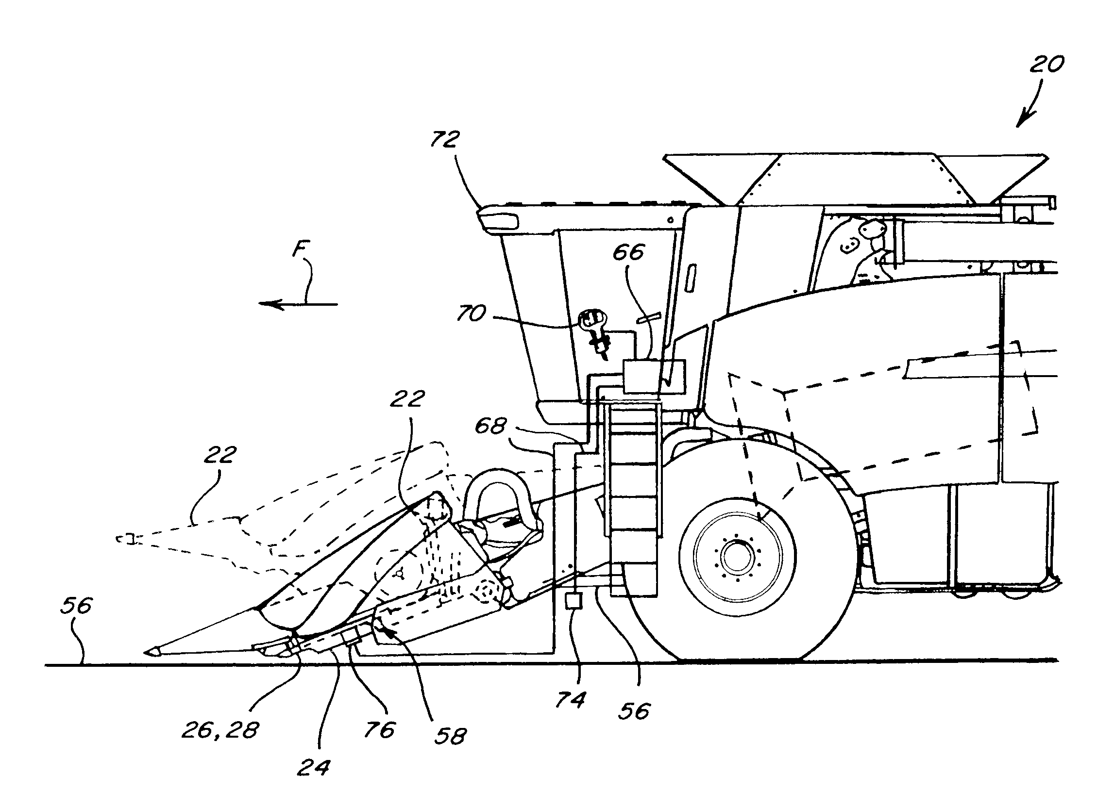
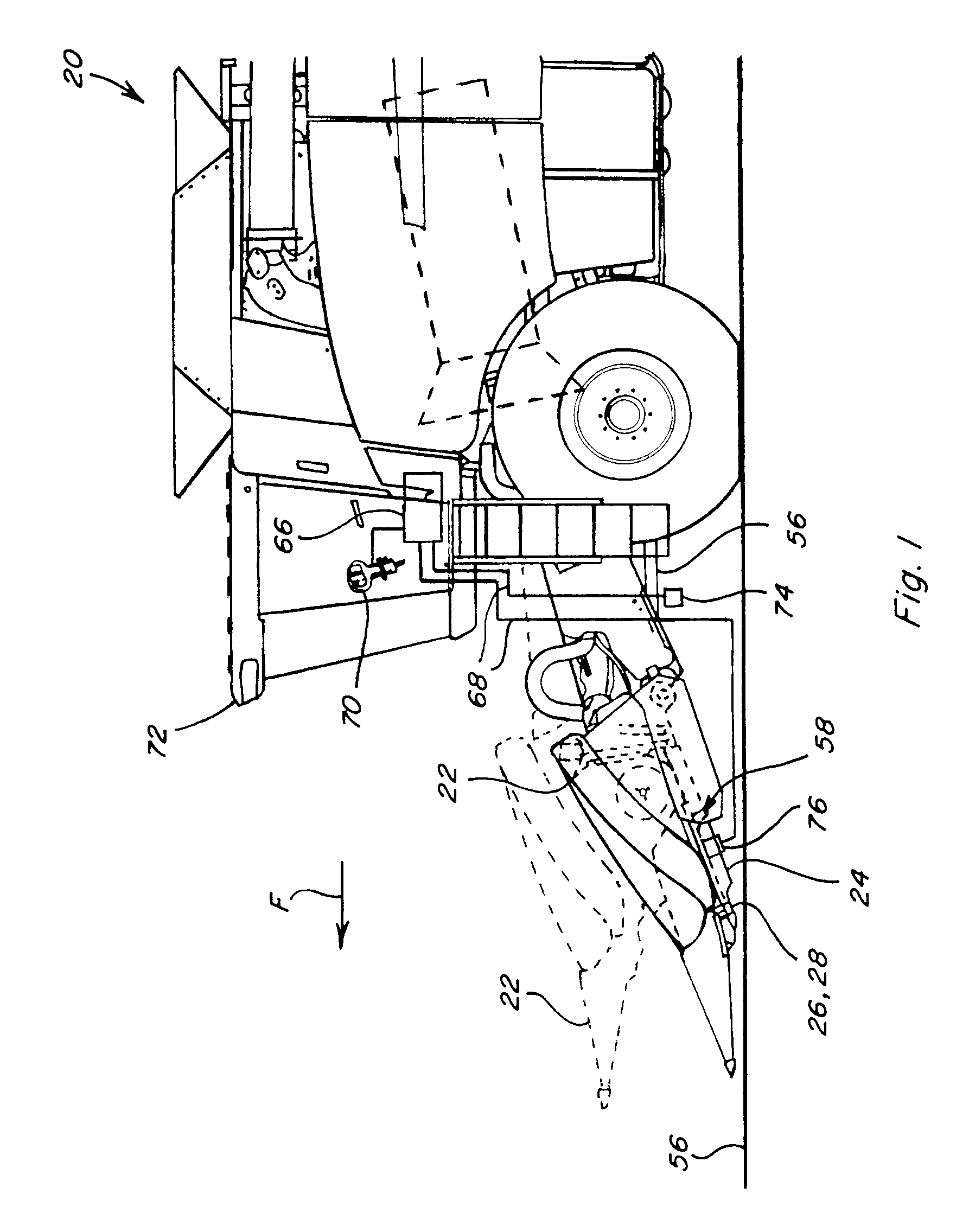
[0019]Referring now to the drawings, in FIG. 1, a representative harvesting machine 20, which is a combine, is shown, including a corn header 22 including a row of harvesting units 24 (see also FIG. 4) constructed and operable according to the teachings of the present invention. Here, harvesting units 24 are configured as corn ear harvesting units operable for receiving and gathering the corn stalks as machine moves in a forward direction, denoted by arrow F, and collapsing the stalks downwardly toward the ground, while removing and collecting the corn ears for further processing by machine 20. To accomplish this, units 24 include harvesting elements, which can include, but are not limited to, conventional gathering chains, snapping rolls, and the like, all supported on a suitable frame of the unit, in the well-known manner. It is contemplated, however, that harvesting units 24 of the invention have utility and can be configured for use to gather and harvest whole or partial stalks ...


PUM


Abstract

The system and method automatically controls the position of at least one deck plate of a harvesting unit of a corn header so as to increase the width of a stalk receiving channel or reduce pinching forces between the plates when entering a stand of corn to facilitate alignment with the corn rows, and to change the position after a suitable time period or other condition or event, to narrow the channel width and / or increase pinching force, to reduce kernel loss while also monitoring forces exerted against the plates by the stalks and responsively adjusting the plate position for maintaining a desired force on the stalks or width.

Description

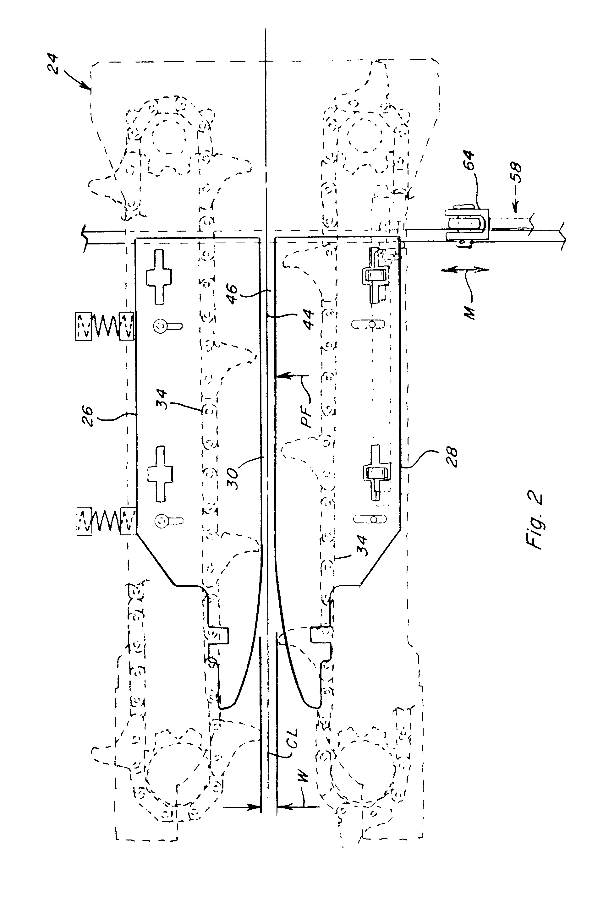
TECHNICAL FIELD[0001]This invention relates generally to controlling the position of at least one of the deck plates of a harvesting unit of a corn header for an agricultural harvesting machine such as a combine, and more particularly, to a system and method for automatically controlling the deck plate position, preferably in cooperation with an opposing biased or spring loaded plate, so as to expand or widen a stalk receiving or picking channel of the unit or reduce pinching forces to facilitate entry or induction of a row of standing corn stalks into the harvesting unit and reduce pushing down of the stalks by the unit, and then, while harvesting, monitoring pinching force exerted against the stalks, and adjusting the plate position for maintaining the channel width or pinching force at a desired or set level for advantages such as maintaining stalk throughput and reducing kernel loss.BACKGROUND ART[0002]Corn plants are typically planted in rows spaced a predetermined distance apa...

Claims


Application Information

Patent Timeline
Patent Type & Authority Patents(United States)
IPC IPC(8): G06F19/00
CPCA01D45/021
Inventor KOWALCHUK, TREVOR L.
Owner BLUE LEAF I P INC
Learn More