Manually guided implement

a technology of manual guide and implement, which is applied in the direction of chain saws, metal sawing accessories, manufacturing tools, etc., can solve the problems of easy limitation of the relative movement of the drive motor and the handle transverse to the longitudinal axis of the horizontally disposed anti-vibration element, and good vibration dampening of the entire system

Active Publication Date: 2012-07-24
ANDREAS STIHL AG & CO KG
View PDF14 Cites 18 Cited by
  • Summary
  • Abstract
  • Description
  • Claims
  • Application Information

AI Technical Summary

Benefits of technology

[0019]The connecting element of the implement of the present application delimits the relative movements between drive motor and handle in a straightforward manner. Consequently, an impermissible movement of the anti-vibration elements transverse to their longitudinal direction is easily avoided. In particular when the connecting element is embodied as an anti-vibration element, the inclined arrangement of the longitudinal axis of the connecting element results in a good vibration dampening of the entire system. At the same time, the connecting element can be easily integrated into the existing installation space, resulting in a small overall size of the implement.
[0021]The angle between the longitudinal axes of the connecting element and of the transverse plane is advantageously less than 80°. The angle is in particular less than 60°, and is advantageously from about 10° to about 45°. With this arrangement, good vibration dampening characteristics of the implement result especially if the connecting element includes an anti-vibration element. At the same time, the relative movement of drive motor and handle transverse to the longitudinal axis of the horizontally disposed anti-vibration element is easily limited.
[0022]The handle is advantageously a rear handle, and the connecting element is advantageously disposed on that side of the transverse plane that faces the rear handle. The operator introduces a greatest part of the operating forces via the rear handle. In particular if the implement is a power saw, during operation, to carry out a back hand cut, pressure is applied to the rear handle and a tubular handle of the implement is pulled. These forces counteract the cutting forces on the tool. As a result, the rear handle moves downwardly relative to the drive motor and thus expands or widens the vibration space. This relative movement is limited by the connecting element. Due to the fact that the connecting element is disposed on that side of the transverse plane that faces the rear handle, there results an arrangement of the connecting element in the region of the greatest relative movement.
[0024]To achieve a good vibration dampening, at least two anti-vibration elements are disposed perpendicular to the longitudinal plane of the implement, whereby a first anti-vibration element is disposed adjacent to the front end of the tubular handle, and one end of a second anti-vibration element is secured to the tubular handle. A straightforward construction of the implement, with good vibration dampening characteristics, results if the connecting element is embodied as an anti-vibration element. The anti-vibration element that is formed as the connecting element is consequently not disposed horizontally, in other words perpendicular to the longitudinal plane, but rather is disposed at an angle. In this way good vibration dampening characteristics can be achieved, while at the same time achieving a limitation of the transverse load of the two horizontally disposed anti-vibration elements. Good vibration dampening characteristics result in particular if the first end of the anti-vibration element that forms the connecting element is secured to the handle housing further from the transverse plane than is the second end, which is secured to the housing. Thus, the upwardly facing side of the anti-vibration element, in the customary disposition of the implement, is inclined toward the front. As a result, the forces that occur during operation can be effectively absorbed. In addition, the installation space that is available can be well utilized.
[0027]The safety cable is advantageously disposed at least partially in the direction of the operating force that during operation acts on the rear handle. The safety cable is advantageously oriented in the direction of the operating force. The safety cable is expediently made of polymeric material, in particular aramid. For a simple securement of the safety cable, a connection fitting can be provided at each end of the safety cable. The connection fittings are advantageously made of polymeric material and are extruded or injected on the safety cable. A reliable securement results when the polymeric material of the connection fitting is molded about the safety cable.
[0028]A first receiving means for the first connection fitting of the safety cable is advantageously formed on the handle housing, and a second receiving means for the second connection fitting of the safety cable is advantageously formed on the housing. A straightforward mounting of the means to protect against over extension is possible if the first connection fitting is cylindrical and the second connection fitting has a multi-sided cross-section, whereby the diameter of the first connection fitting is less than the smallest diameter of the multiple sides of the second connection fitting. The multi-sided cross-section of the second connection fitting ensures that the safety cable cannot twist during operation. Due to the fact that the first connection fitting has a smaller diameter than the smallest diameter of the second connection fitting, the first connection fitting can be inserted through the receiving means of the second connection fitting and can be fixed in the receiving means for the first connection fitting. This results in a straightforward and reliable fixation of the means to protect against over extension.

Problems solved by technology

In particular when the connecting element is embodied as an anti-vibration element, the inclined arrangement of the longitudinal axis of the connecting element results in a good vibration dampening of the entire system.
At the same time, the connecting element can be easily integrated into the existing installation space, resulting in a small overall size of the implement.
At the same time, the relative movement of drive motor and handle transverse to the longitudinal axis of the horizontally disposed anti-vibration element is easily limited.

Method used


Image

  • Manually guided implement
  • Manually guided implement
  • Manually guided implement

Examples


Embodiment Construction

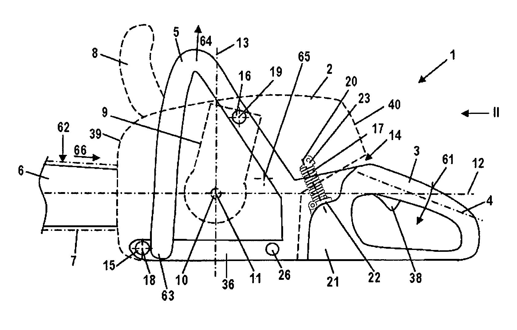
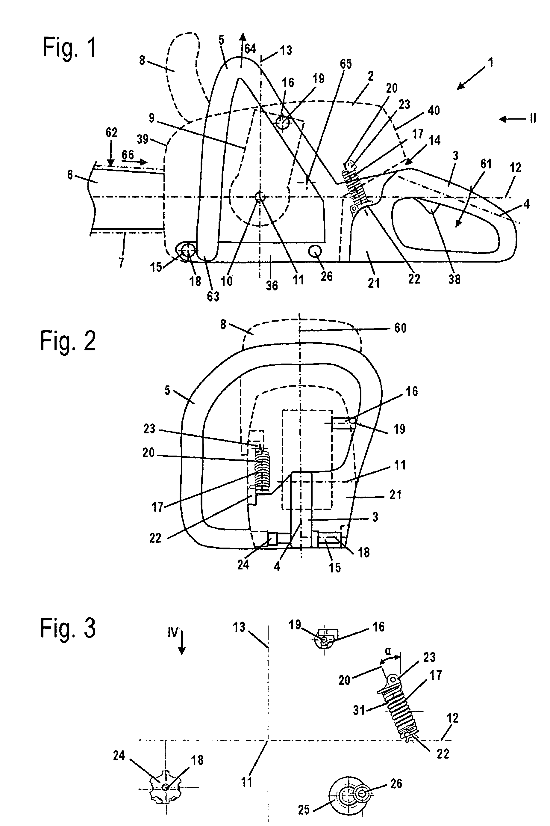
[0030]Referring now to the drawings in detail, as an exemplary embodiment for a manually-guided implement, FIG. 1 shows a power saw 1. However, the present invention can also be used with other manually-guided, and in particular portable, implements, such as cut-off machines or the like. The power saw 1 has a housing 2 in which is disposed a drive motor 9, which is in particular embodied as an internal combustion engine, and is advantageously a single cylinder engine. The drive motor 9 is in particular a two-cycle engine or a mixture-lubricated four-cycle engine. The drive motor 9 has a drive shaft 10 that, when the drive motor 9 is embodied as an internal combustion engine, is the crankshaft, and is rotatably driven about an axis of rotation 11. The drive shaft 10 rotatably drives a non-illustrated pinion. The power saw 1 has a guide bar 6 on which a saw chain 7 circulates. The saw chain 7 is driven in a circulating manner by the drive shaft 10 via the non-illustrated pinion. The g...


PUM

PropertyMeasurementUnit
angleaaaaaaaaaa
angleaaaaaaaaaa
angleaaaaaaaaaa

Abstract

A manually guided implement, such as a power saw, a cut-off machine, or the like, having a drive motor for driving a tool of the implement. The drive motor has a drive shaft that is rotatably driven about an axis of rotation. The implement has a handle on which is disposed at least one control handle for the drive motor. Formed between the handle and the drive motor is a vibration space that is spanned by at least one anti-vibration element, at least one of which includes a coil spring, the longitudinal axis of which is disposed approximately perpendicular to a longitudinal plane of the implement. The vibration space is spanned by at least one connecting element, the longitudinal axis of which is inclined relative to a transverse plane of the implement that is disposed perpendicular to the longitudinal plane.

Description

[0001]The instant application should be granted the priority date of May 11, 2007, the filing date of the corresponding German patent application DE 10 2007 022 155.2.BACKGROUND OF THE INVENTION[0002]The present invention relates to a manually guided implement, such as a power saw, a cut-off machine, or the like.[0003]With manually guided implements, it is known to mount the drive motor in such a way that it is vibration-neutralized from the handles that serve to guide the implement. It is also known to use anti-vibration elements that include coil springs. Anti-vibration elements having a coil spring result in a good vibration dampening. Anti-vibration elements that include a coil spring are customarily horizontally disposed, as viewed in the working direction, between the drive motor and the handle. Such an arrangement of the anti-vibration elements is known, for example, from U.S. Pat. No. 7,219,433.[0004]During operation, handle and drive motor carry out relative movements in th...

Claims


Application Information

Patent Timeline
Patent Type & Authority Patents(United States)
IPC IPC(8): B27B17/02B25D17/24
CPCB27B17/0033
Inventor GUIP, ANDREASMENZEL, JOHANNESLUX, HELMUTWOLF, GUNTER
Owner ANDREAS STIHL AG & CO KG
Why Eureka
Try Eureka