
Differential-pressure flowmeter and flow-rate controller

a flowmeter and flow rate controller technology, applied in the direction of valve operating means/releasing devices, process and machine control, instruments, etc., can solve the problem of unstable pressure measurement by the pressure sensor, and achieve accurate and stable pressure measurement, reduce the difference, and eliminate the effect of differences

Active Publication Date: 2012-07-24
SURPASS IND
View PDF22 Cites 34 Cited by
  • Summary
  • Abstract
  • Description
  • Claims
  • Application Information

AI Technical Summary

Benefits of technology

The present invention provides a differential-pressure flowmeter and a flow-rate controller that can reduce the difference between the ambient temperature of one pressure sensor and the ambient temperature of the other pressure sensor, allowing for accurate and stable pressure measurement and flow-rate control. The flow-rate controller includes a body with a main fluid channel through which a fluid flows, and two pressure sensors held by the body. A temperature balancer composed of a material with high thermal conductivity is embedded in a recess that is formed below the two pressure sensors. The flow-rate controller also includes a constricted section that minimizes heat transmission from the control board and the motor serving as a heat source to the pressure sensors. The flow-rate controller can be connected to a differential-pressure flowmeter and a base component positioned between the two pressure sensors is preferably provided with at least one slit that extends therethrough in a thickness direction of the base component. The flow-rate controller can also include a cooling groove that allows for heat dissipation and a groove that allows a front surface and a rear surface to communicate with each other. These features enhance the accuracy and stability of fluid flow-rate control and allow for the reduction of the difference between the ambient temperature of one pressure sensor and the ambient temperature of the other pressure sensor.

Problems solved by technology

Therefore, when a temperature difference occurs between the ambient temperature of one of the pressure sensors and the ambient temperature of the other pressure sensor as a result of a change in the ambient temperature of only the one pressure sensor, the pressure measurement by the pressure sensors becomes unstable, possibly causing a malfunction.

Method used


Image

  • Differential-pressure flowmeter and flow-rate controller
  • Differential-pressure flowmeter and flow-rate controller
  • Differential-pressure flowmeter and flow-rate controller

Examples


Embodiment Construction

[0033]A differential-pressure flowmeter and a flow-rate controller according to an embodiment of the present invention will be described below with reference to FIGS. 1 to 5C.

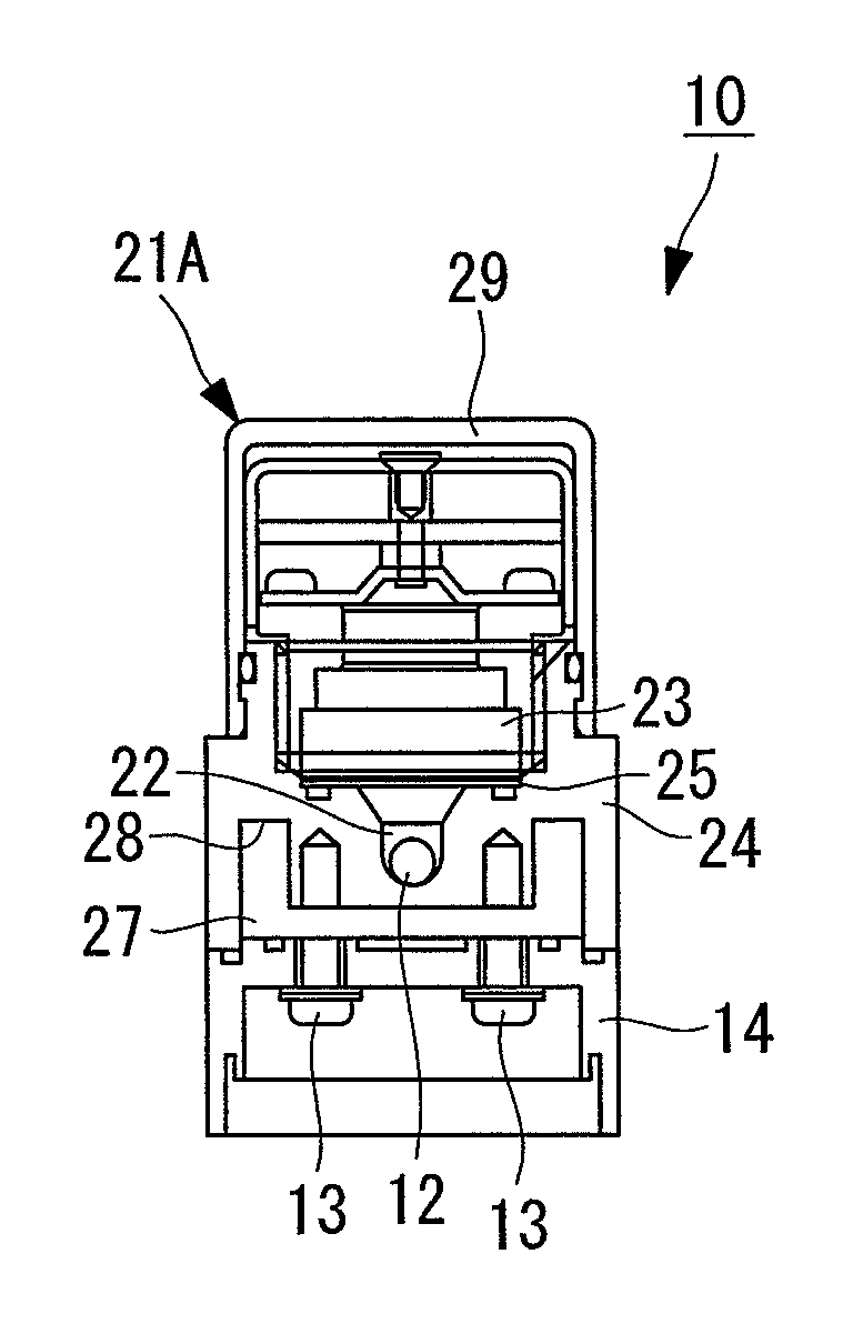
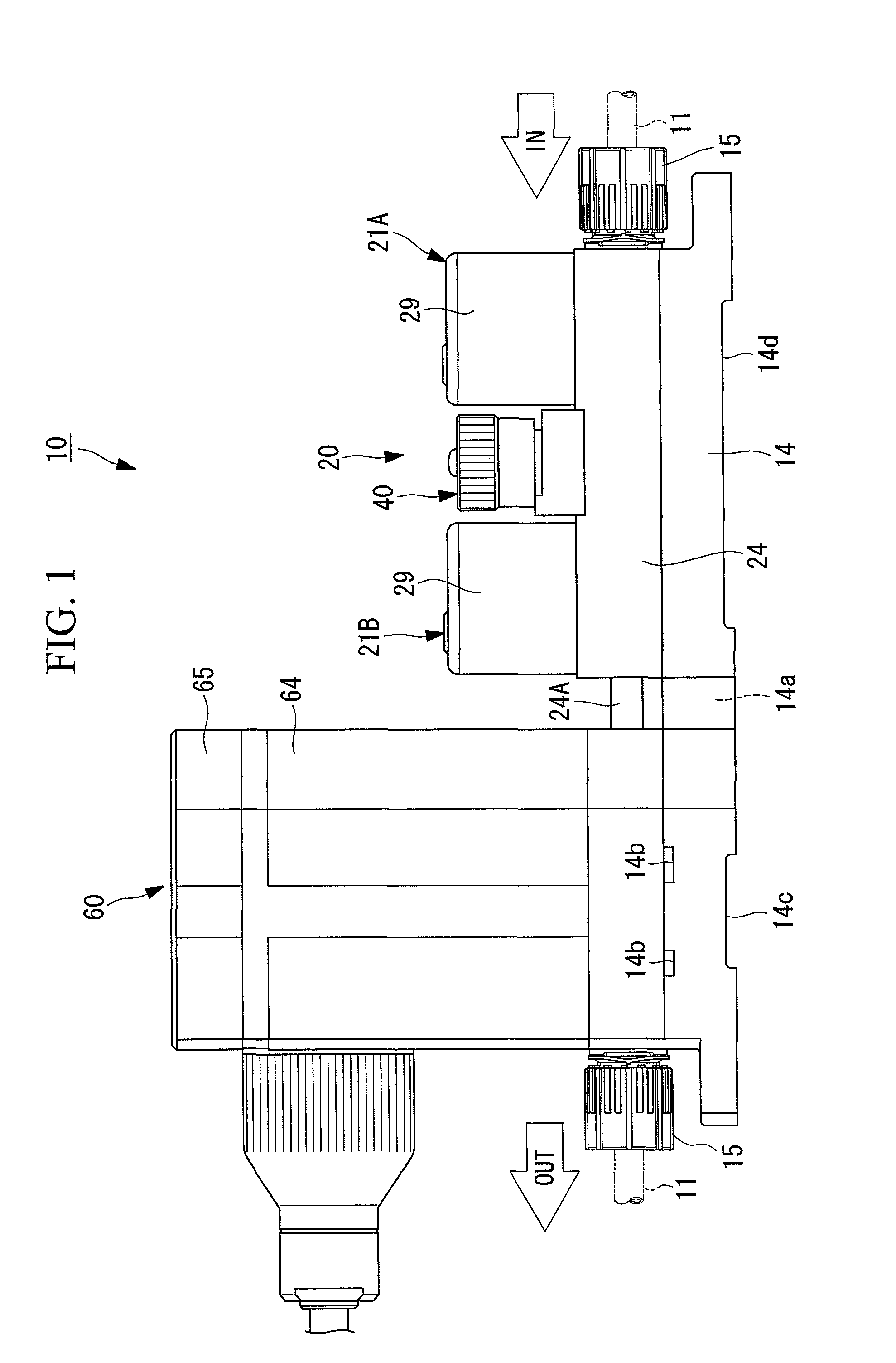
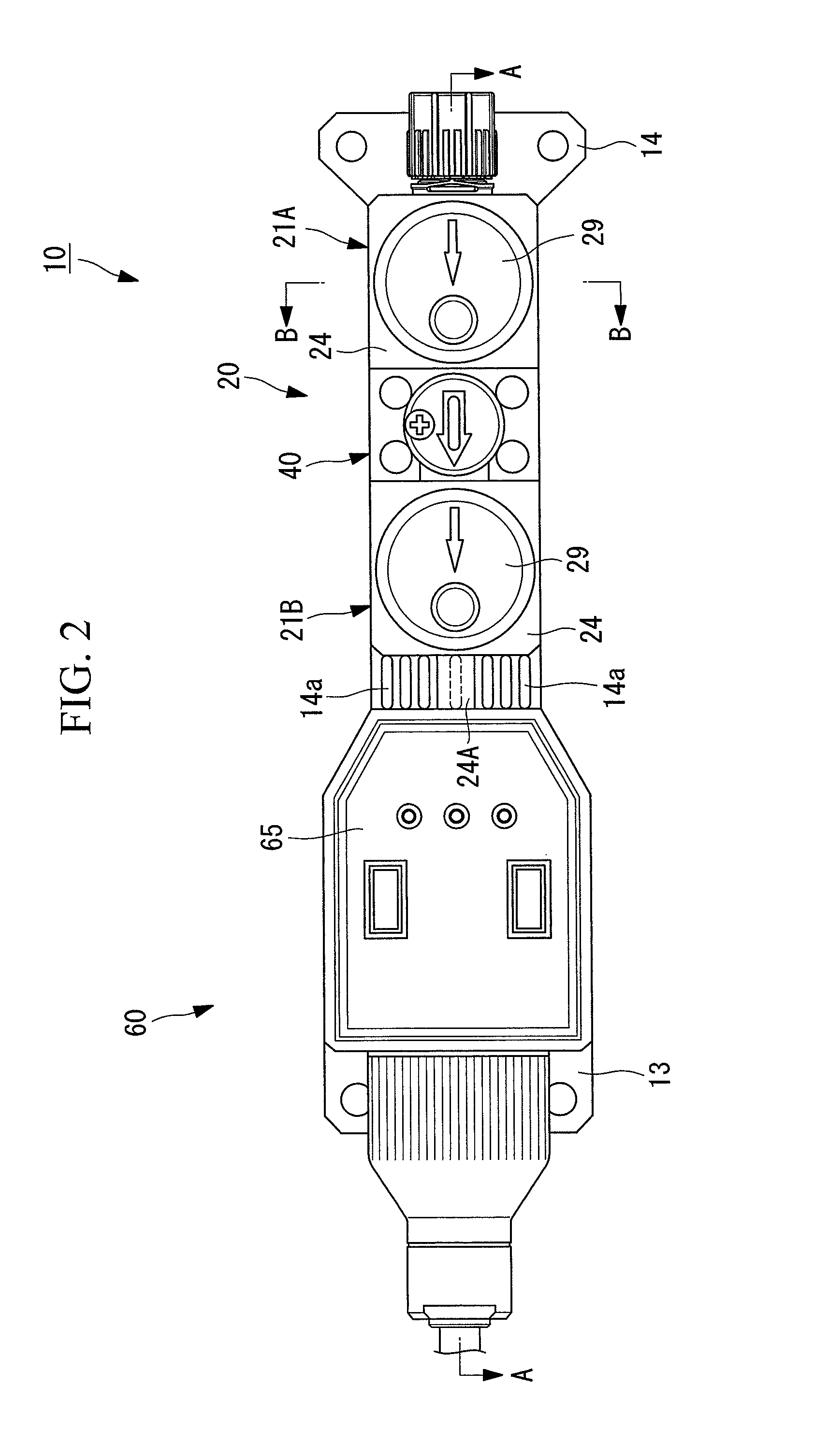
[0034]FIG. 1 is a front view of the flow-rate controller according to this embodiment. FIG. 2 is a plan view of FIG. 1. FIG. 3 is a sectional view taken along line A-A in FIG. 2. FIG. 4 is a sectional view taken along line B-B in FIG. 2. FIG. 5A is a plan view illustrating a temperature balancer incorporated in the differential-pressure flowmeter according to this embodiment. FIG. 5B is a front view of the temperature balancer. FIG. 5C is a side view of the temperature balancer.

[0035]A flow-rate controller 10 is a flow-rate controlling device that is incorporated in a pipe 11 communicating with a main fluid channel 12, to be described later, and keeps the fluid flow rate of a liquid (such as a chemical solution) flowing through the main fluid channel 12 constant. The flow-rate controller 10 mainly includes a di...


PUM


Abstract

A differential-pressure flowmeter that can reduce (eliminate) a difference between the ambient temperature of one pressure sensor and the ambient temperature of another pressure sensor so as to allow for accurate and stable pressure measurement is provided, and a flow-rate controller equipped with such a differential-pressure flowmeter is provided. Provided are a body having a main fluid channel through which a fluid, whose pressure is to be measured, flows, and two pressure sensors held by the body and arranged in series relative to the main fluid channel, and a temperature balancer composed of a material with high thermal conductivity is accommodated in a recess that is formed in the body located below the two pressure sensors.

Description

BACKGROUND OF THE INVENTION[0001]1. Field of the Invention[0002]The present invention relates to differential-pressure flowmeters and flow-rate controllers used in fluid transport pipes in various industrial fields, such as chemical factories, semiconductor manufacturing, food manufacturing, and biotechnology.[0003]This application is based on Japanese Patent Application No. 2009-024714, the content of which is incorporated herein by reference.[0004]2. Description of Related Art[0005]Japanese Unexamined Patent Application, Publication No. 2009-2901 discloses a known example of a differential-pressure flowmeter and a flow-rate controller used in fluid transport pipes in various industrial fields, such as chemical factories, semiconductor manufacturing, food manufacturing, and biotechnology.[0006]Two pressure sensors constituting the differential-pressure flowmeter and the flow-rate controller disclosed in Japanese Unexamined Patent Application, Publication No. 2009-2901 each have a c...

Claims


Application Information

Patent Timeline
Patent Type & Authority Patents(United States)
IPC IPC(8): F16K31/12
CPCF16K37/0066G01F1/42G01F1/50G01F15/005G01F15/02F16K37/005G05D7/0635Y10T137/7758Y10T137/7762Y10T137/6525Y10T137/7761
Inventor IGARASHI, HIROKI
Owner SURPASS IND
Learn More