Insertion of vibration-damping elements in prosthetic systems for the manipulation and damping of natural frequencies

a technology of vibration-damping elements and prosthetic systems, which is applied in the field of hip joint prosthesis, can solve the problems of unfavorable solid-body friction between sliding partners, considerable personal restrictions, etc., and achieve the effects of reducing sound pressure, good damping properties, and less disturbing

Inactive Publication Date: 2012-07-24
CERAMTEC
View PDF132 Cites 14 Cited by
  • Summary
  • Abstract
  • Description
  • Claims
  • Application Information

AI Technical Summary

Benefits of technology

The patent text describes a way to reduce the vibrations and noise of a prosthetic system by adding damping elements made of a special material. These damping elements can be placed at the points where different components of the system are connected. This helps to shift the characteristic frequencies of the system and reduce the amplitudes of the vibrations. The damping elements can be arranged either serially or in parallel in the system. This technology can make the prosthetic system quieter and more comfortable for users.

Problems solved by technology

The technical problem addressed in this patent is the occurrence of solid-body friction and stick-slip effect in hip-joint prostheses, which can result in the emission of vibrations that cause discomfort and potential acoustic perception for the patient.

Method used


Image

  • Insertion of vibration-damping elements in prosthetic systems for the manipulation and damping of natural frequencies
  • Insertion of vibration-damping elements in prosthetic systems for the manipulation and damping of natural frequencies
  • Insertion of vibration-damping elements in prosthetic systems for the manipulation and damping of natural frequencies

Examples


Embodiment Construction

[0034]The prior art and the invention are explained in greater detail in the following with the aid of figures.

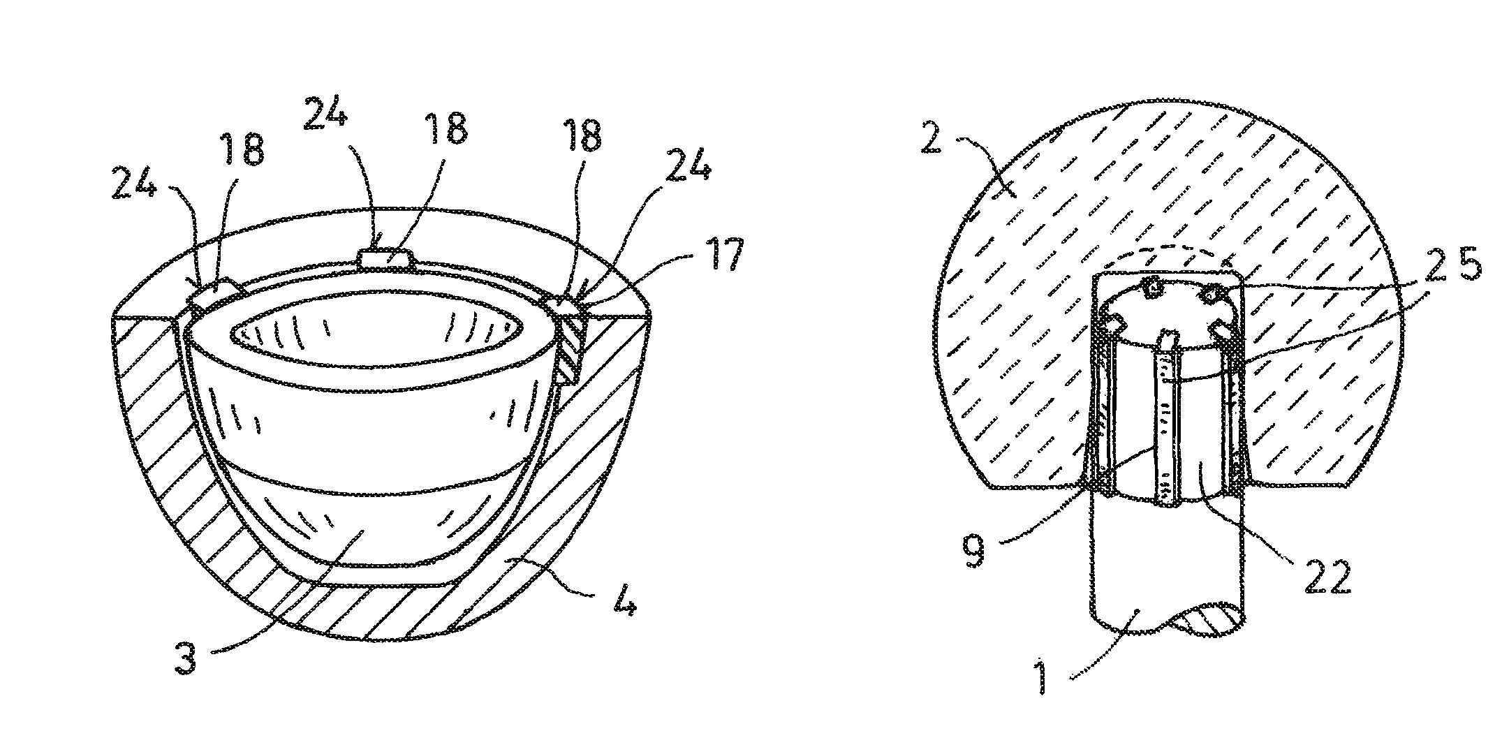
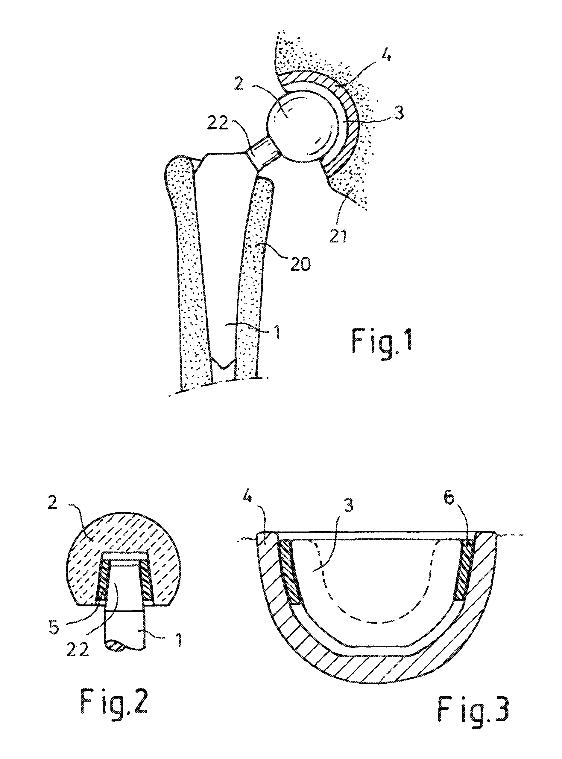
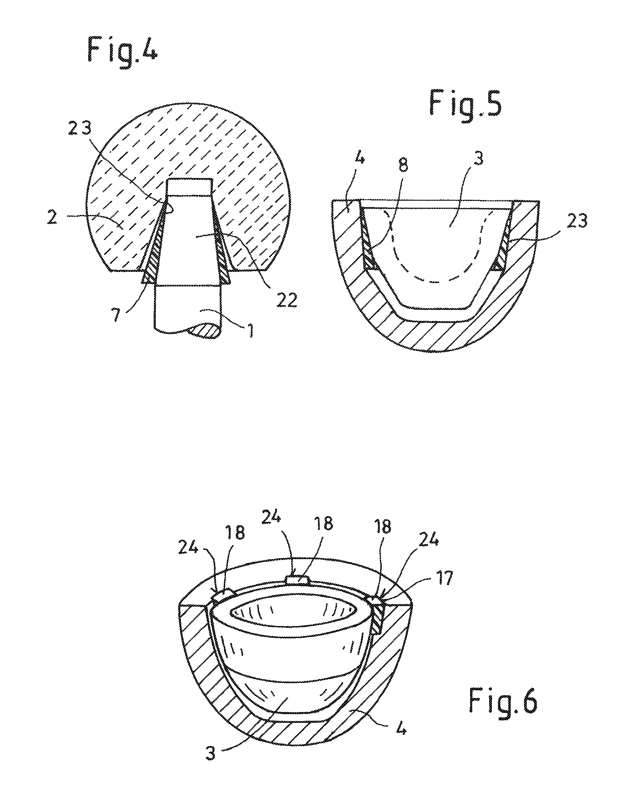
[0035]FIG. 1 shows the prior art. A hip prosthesis as a rule consists of a shaft 1 coupled with a ball head 2 and of a hip socket 4 coupled with a socket insert 3. The shaft 1 and the hip socket 4 are connected to the body of the patient as a result of growing into the femur 20 and the pelvic bone 21 respectively and are carriers for the ball head 2 and the socket insert 3 respectively. The ball head 2 is rotatably mounted in the hemispherical recess of the socket insert 3.

[0036]FIG. 2 shows a ball head 2 which is connected to the shaft head 22 of a shaft 1 by way of an adapter sleeve 5. The shaft head 22 is formed as a cone. In adaptation to this, the inside of the adapter sleeve 5 is also formed as a cone. Set on the outside of the adapter sleeve, likewise formed as a cone, is the ball head 2 with its inner cone face. In order to suppress the transmission of vibrations, t...


PUM


Abstract

A hip joint prosthesis with a shaft fastened on the shaft head of which there is a ball head which in turn is inserted in a rotatable manner in the spherical recess of a socket insert and the socket insert is coupled with a hip socket wherein the shaft can be implanted in the femur and the hip socket can be implanted in the pelvic bone. To avoid transmission of vibrations, damping elements of a vibration-damping material are arranged at the coupling points of the shaft head with the ball head and/or of the socket insert with the hip socket.

Description


Claims


Application Information

Patent Timeline
Owner CERAMTEC
Why Eureka
Try Eureka