Eureka AIR delivers breakthrough ideas for toughest innovation challenges, trusted by R&D personnel around the world.

Resonator

a resonator and resonator technology, applied in the field of resonators, can solve the problems of large installation space for a resonator, increase the installation space of the resonator, and difficulty in maintaining the desired sound pressure suppression effect for a substantial period of time, and achieve the effect of small installation space, efficient reduction of the sound pressure of the target sound, and large sound pressur

Inactive Publication Date: 2009-06-02
TOYODA GOSEI CO LTD
View PDF29 Cites 14 Cited by
  • Summary
  • Abstract
  • Description
  • Claims
  • Application Information

AI Technical Summary

Benefits of technology

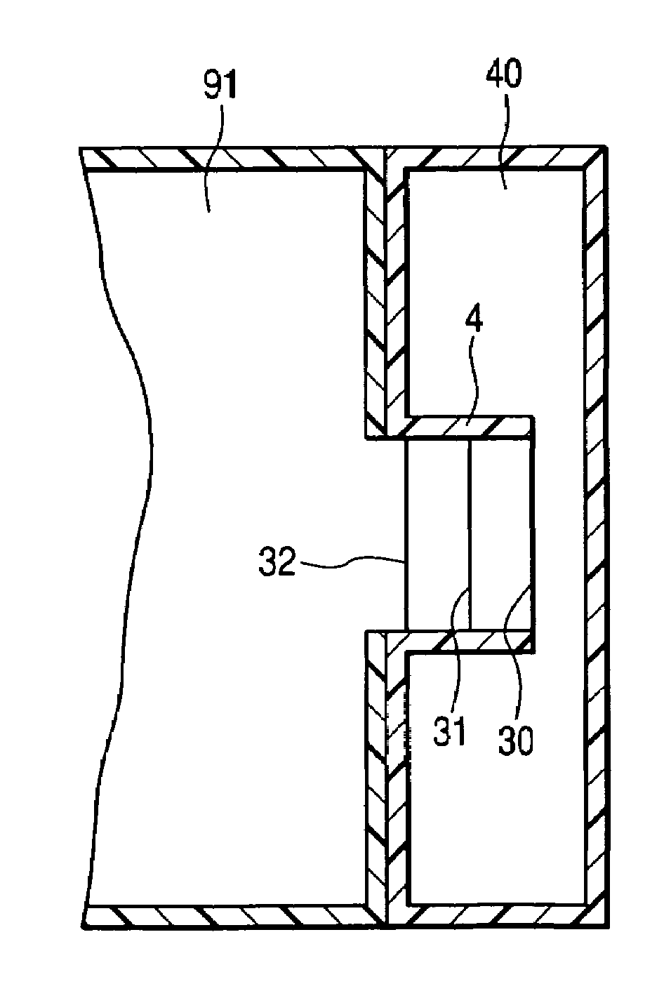
[0015]Thus, the natural frequency of the partitioning member of the resonator according to the invention is set lower than the frequency of the silencing target sound of the intake noise. Even when the tension of the partitioning member is decreased and the natural frequency of the partitioning member lowered, the mass effect of the partitioning member is not degraded. The resonator according to the invention thus readily maintains a desired sound pressure suppression effect.
[0016]For the resonator according to the invention, the internal attenuation of the partitioning member itself produces unsharpened echo resonance (a portion where the sound pressure appearing on high frequencies or low frequencies of the resonance frequency is high). This makes it possible to reduce the sound pressure of echo resonance.
[0018]This configuration embodies the resonator according to the invention as a Helmholtz resonator. According to the configuration, it is possible to shift the natural frequency of a resonator toward lower frequencies than a Helmholtz resonator of the same shape. It is further possible to more compact resonator than a Helmholtz resonator to which the frequency of the same silencing target sound is set.
[0020]The silencing effect of the resonator according to the invention depends on the volume of the cavity chamber, not on its shape. Thus, according to the invention, a resonator may be designed in any shape as long as its volume is kept constant. For example, the cavity chamber may be provided having a large width and small thickness. Thus adds to space saving. By tailoring the shape of the cavity chamber to the shape of the pipe section of the intake system, the freedom of arrangement of the resonator is dramatically enhanced.
[0024](7) Preferably, the branch pipe is arranged at a site where the antinode of a standing wave of the silencing target sound of the intake noise is positioned in the pipe section. The antinode of a standing wave has a large sound pressure. With this configuration, it is possible to more efficiently lower the sound pressure of the silencing target sound.
[0025]According to the invention, it is possible to provide a resonator having a small installation space that readily maintains a desired sound pressure suppression effect.

Problems solved by technology

Such a related art resonator has a disadvantage that a larger installation space for a resonator is required in case the sound pressure of a lower frequency component with lower frequency of intake noise is to be suppressed.
This increases the installation space for the resonator.
A problem with the resonator described in JP-UM-A-2-080710 is that it is difficult to maintain a desired sound pressure suppression effect for a substantial period of time.
Thus, it is difficult for the resonator described in JP-UM-A-2-080710 to maintain a desired sound pressure suppression effect for a substantial period of time.

Method used


Image

  • Resonator
  • Resonator
  • Resonator

Examples


examples

[0076]Measurement tests such as an acoustic excitation test and a numerical value test (transfer-matrix method) executed on the resonator of the embodiment will be described below.

first example

[0077]The acoustic excitation test executed on the resonator 1 shown in FIG. 7 will be described.

[0078][Test sample]

[0079]The specifications of the resonator 1 shown in FIG. 7 will be described. The volume V of the cavity chamber is 0.58 l (liters). The inner diameter D of the cavity chamber is 84 mm. The axial length l of the communication pipe 4 is 17.5 mm. The inner diameter d of the communication pipe 4 is 42 mm. The spring constant k of the diaphragms 30 through 33 is 34.7 N / m. The density p of the diaphragms 30 through 33 is 8.70×10² kg / M3. The thickness t of the diaphragms 30 through 33 is 0.5 mm. The resonator 1 having such specifications is called Example 1.

[0080][Test Method]

[0081]Next, the acoustic excitation test will be described. The acoustic excitation test uses a straight tubular pipe having an entire length of 0.6 m whose ends are open, a loudspeaker, and a microphone. To the side wall at the middle section of the straight tubular pipe branches the resonator 1. At o...

example 2

[0088]Calculation result of the transfer-matrix method executed on the test samples shown below will be described.

[0089][Test Sample]

[0090]Specifications of test samples will be described. FIG. 9 is a schematic view of the test sample in Example 2-1. FIG. 10 is a schematic view of the test sample in Example 2-2. FIG. 11 is a schematic view of the test sample in Comparison Example 2-1. FIG. 12 is a schematic view of the test sample in Comparison Example 2-2. In these drawings, sections corresponding to FIG. 7 are given same signs.

[0091]Example 2-1 shown in FIG. 9 arranges diaphragms 30a through 30i in Comparison Example 2-1 shown in FIG. 11 (side branch resonator). A branch pipe 2 shows a shape of a cylinder with a bottom. The spring constant k of the diaphragms 30a through 30i is 139 N / m. The density p of the diaphragms 30a through 30i is 8.70×10² kg / M3. The thickness t of the diaphragms 30a through 30i is 0.5 mm. The inner diameter d′ of the branch pipe 2 in Example 2-1 (FIG. 9) an...


PUM


Abstract

A resonator is arranged in an intake system including a pipe section for partitioning an intake port from an intake passage that communicates the intake port with a combustion chamber of an engine, the resonator including: a branch pipe having one end branching to the pipe section and the other end closed so that a silencing chamber is defined therein; and at least one partition wall for partitioning the silencing chamber into at least one pneumatic spring chamber, the partition wall having a natural frequency lower than the frequency of silencing target sound of intake noise propagated from the intake passage.

Description

BACKGROUND OF THE INVENTION[0001]1. Field of the Invention[0002]The present invention relates to a resonator for suppressing the intake noise of an intake system for a vehicle.[0003]2. Related Art[0004]A side branch resonator or a Helmholtz resonator has been used in the related art in order to suppress intake noise of an intake system. Such a related art resonator has a disadvantage that a larger installation space for a resonator is required in case the sound pressure of a lower frequency component with lower frequency of intake noise is to be suppressed.[0005]For a side branch resonator, the natural frequency of sound that can be silenced by resonance depends on the length of the side branch. Meanwhile, the wavelength becomes longer as the signal component becomes lower. In order to suppress a low frequency component by using a side branch resonator, the side branch length must be increased. This increases the installation space for the resonator.[0006]For a Helmholtz resonator, ...

Claims


Application Information

Patent Timeline
Patent Type & Authority Patents(United States)
IPC IPC(8): F01N1/02F02M35/10
CPCF02M35/1266F02M35/1272F02M35/14
Inventor OKAWA, SHINTAROUSAWATARI, TOMOYUKIHIROSE, YOSHIKAZUTOYODA, MINORUHATTORI, MASARUSUZUKI, TATSUOIWAO, HIROSHIOGASAWARA, YUTAKA
Owner TOYODA GOSEI CO LTD
Why Eureka
Eureka Blog
Learn More