Dynamic positioning of fans to reduce noise

Active Publication Date: 2018-04-19
LENOVO GLOBAL TECH INT LTD
View PDF0 Cites 15 Cited by
  • Summary
  • Abstract
  • Description
  • Claims
  • Application Information

AI Technical Summary

Benefits of technology

[0004]One embodiment of the present invention provides a method comprising sensing sound pressure at a specified location, and a controller a

Problems solved by technology

As the workload on the computer increases, the amount of heat generated by computer will also increase, therefore requiring an increase in air flow through the computer.
When numerous computers are located in the same plac

Method used


Image

  • Dynamic positioning of fans to reduce noise
  • Dynamic positioning of fans to reduce noise
  • Dynamic positioning of fans to reduce noise

Examples


Example

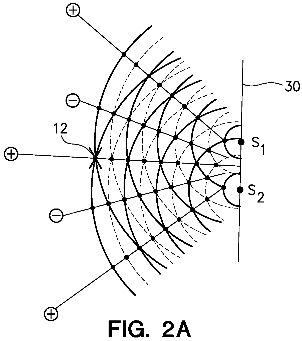
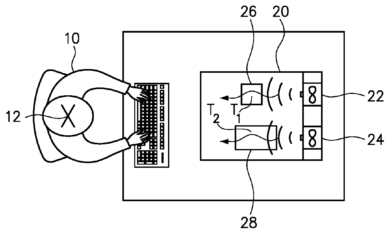
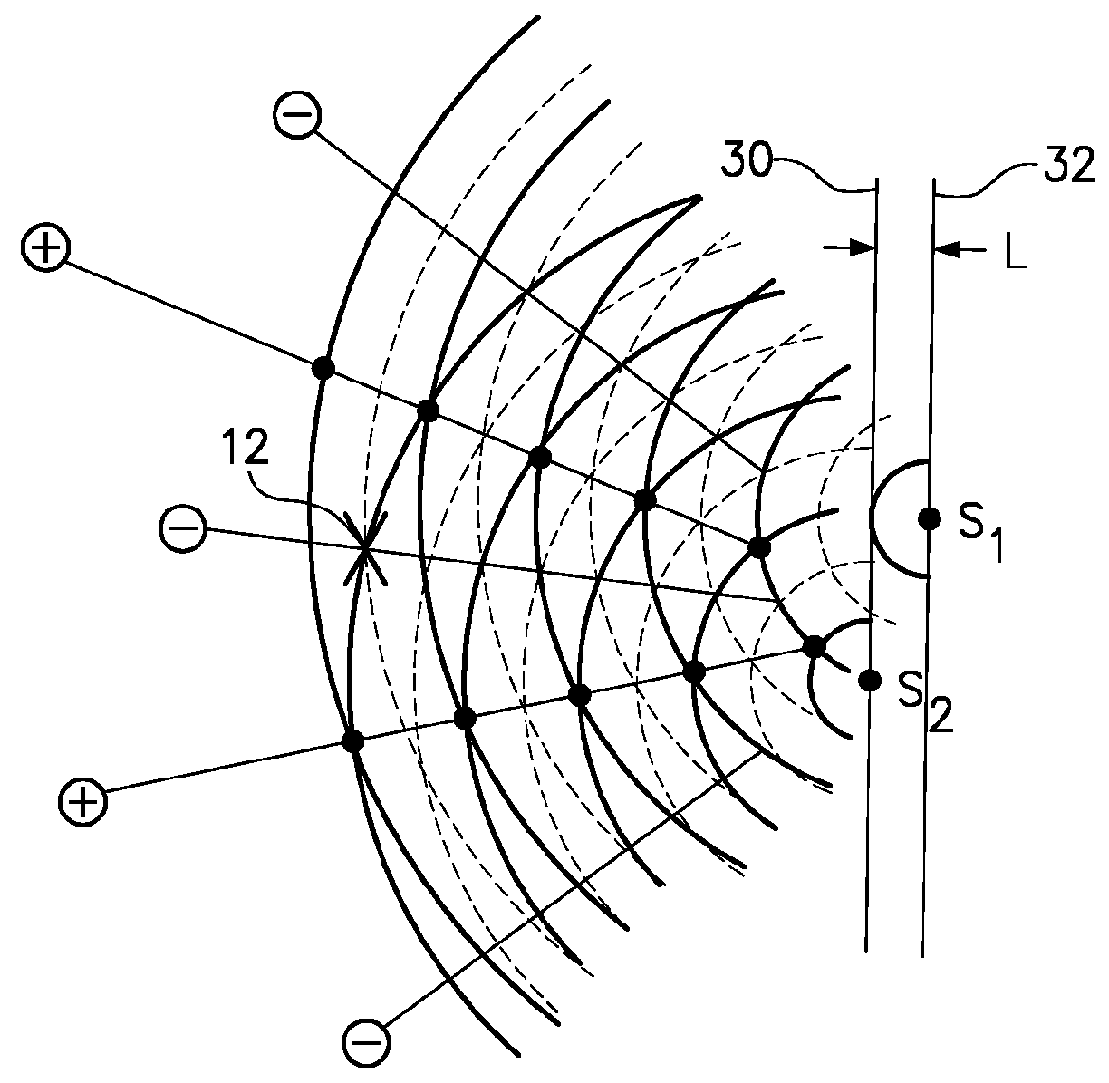
[0015]One embodiment of the present invention provides a method comprising sensing sound pressure at a specified location, and a controller automatically adjusting a position of one or more fans among a plurality of fans to reduce the sound pressure sensed at the specified location.

[0016]Sound pressure may be measured by a microphone. A microphone is a transducer that converts sound into an electrical signal. Accordingly, the microphone may generate an electrical signal indicating the instantaneous sound pressure at the location of the microphone. The specified location of the microphone may be any desired location where the sound of multiple fans may be an issue. For example, a microphone may be positioned at any fixed point in a room or area containing the fans, or a microphone may be secured to a person working in, and perhaps moving about within, the room or area. For the purpose of reducing the amount of noise experienced by a person, the microphone is preferably positioned whe...


PUM


Abstract

A method includes sensing sound pressure at a specified location, and a controller automatically adjusting a position of one or more fans among a plurality of fans to reduce the sound pressure sensed at the specified location. The position of the one or more fans may, for example, be adjusted using an actuator to change the distance from the fan and the specified location, which may be a location of a user. Optionally, the method may further include the controller automatically adjusting a speed of one or more fans among the plurality of fans to reduce the sound pressure sensed at the specified location. The position and speed of one or more fans may be adjusted to provide destructive interference at the specified location.

Description

BACKGROUNDField of the Invention[0001]The present invention relates to methods and devices for reducing noise produced by multiple fans.Background of the Related Art[0002]Computers perform many important and valuable tasks, but produce heat that must be removed from the computer to avoid damage to the components. The simplest and most common means for removing this heat is forced air circulation through a computer enclosure. For this purpose, fans may be installed in each computer or each multi-node chassis in order to assure that an adequate volume of air flows through each device. The speed of a fan, such as the rotational speed of an axial fan, will generally increase to prevent a critical component, such as a central processing unit, from reaching a high temperature threshold. As the workload on the computer increases, the amount of heat generated by computer will also increase, therefore requiring an increase in air flow through the computer. The actual speed of a fan is furthe...

Claims


Application Information

Patent Timeline
IPC IPC(8): G10K11/00F04D19/00F04D15/00G10K11/175
CPCG10K11/004G10K11/175F04D15/00F04D19/002G10K11/161G10K11/178G10K2210/11F05D2270/333F04D25/166F04D27/001F04D27/004Y02B30/70F04D29/665F04D29/663G06F1/1633H04R1/22H04R3/00H05K7/20209
Inventor YOUNG, BRYAN L.CUDAK, GARY D.ROSE, AMY L.LEE-BARON, JENNIFER J.CROWE, JOHN S.PETERSON, NATHAN J.
Owner LENOVO GLOBAL TECH INT LTD
Why Eureka
Try Eureka