
Method and apparatus for automatically identifying electrical parameters in a sensor-less PMSM

a sensor-less motor and automatic identification technology, applied in the direction of motor/generator/converter stopper, pulse technique, dynamo-electric converter control, etc., can solve the problems of not being suitable for sensor-less motors, requiring knowledge of other machine parameters, and most model-based methods fail at low and zero speeds, etc., to achieve accurate model saturation effects and effective parameter estimation

Active Publication Date: 2012-07-24
ROCKWELL AUTOMATION TECH
View PDF9 Cites 28 Cited by
  • Summary
  • Abstract
  • Description
  • Claims
  • Application Information

AI Technical Summary

Benefits of technology

Enables comprehensive and accurate determination of motor parameters, including q-axis self-inductance over a range of currents, facilitating high-performance control and minimizing user input, while allowing precise resistance measurements and controlled startup of the motor.

Problems solved by technology

The signal injection method does not need machine parameters; however, it has limitations caused by the extra losses due to the injected high frequency carriers.
Consequently, most model-based methods fail at low and zero speeds because back-EMF is speed dependent.
Current methods to collect these parameters, unfortunately, either are not suitable for sensor-less motors, require knowledge of other machine parameters and are thus not comprehensive, or provide for incomplete collection of the necessary parameters, treating self-inductances as constants.

Method used


Image

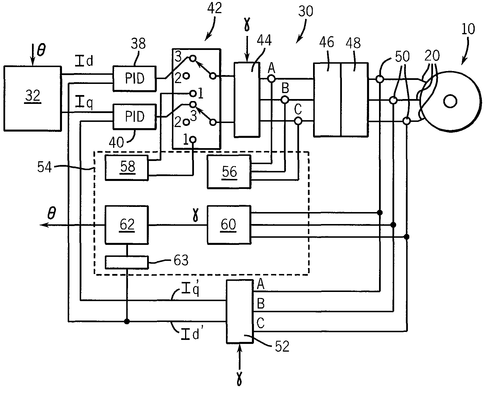
  • Method and apparatus for automatically identifying electrical parameters in a sensor-less PMSM
  • Method and apparatus for automatically identifying electrical parameters in a sensor-less PMSM
  • Method and apparatus for automatically identifying electrical parameters in a sensor-less PMSM

Examples


Embodiment Construction

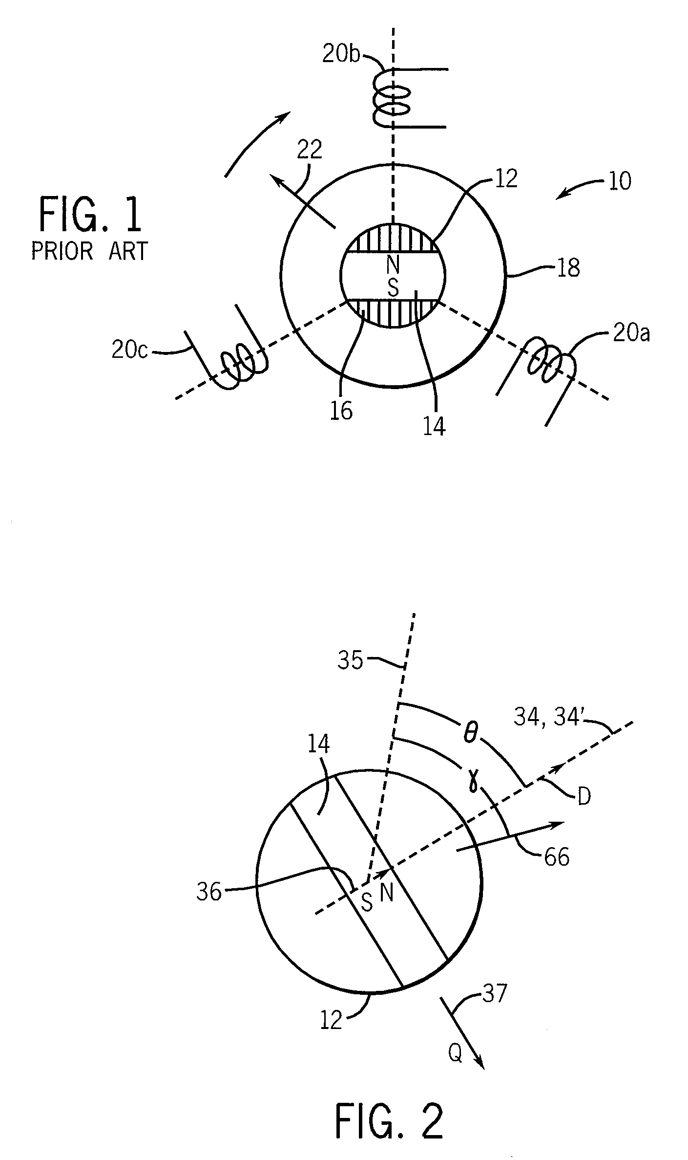
[0040]Referring now to FIG. 1, a sensor-less PMSM motor 10 provides a rotor 12 attached to a rotatable shaft (not shown) for rotation about an axis through the center of the rotor 12 perpendicular to the plane of the figure. The rotor 12 includes a permanent magnet 14 and ferromagnetic flux directors 16. For clarity, a rotor having a single pole pair (e.g. only a single north and south pole) is shown; however, it will be understood that the present invention is equally applicable to multi-pole rotors.

[0041]The rotor 12 may be surrounded by a stator 18 having one or more coils 20a, 20b, and 20c shown here positioned at regular angles of 120° about the rotor 12. Again additional coils may be provided according to techniques well known in the art for motors having larger numbers of poles.

[0042]Generally, appropriately phased signals may be applied to each of coils 20a, 20b and 20c to produce a rotating magnetic field vector 22 synchronously attracting the rotor 12 to drive the motor 10...


PUM


Abstract

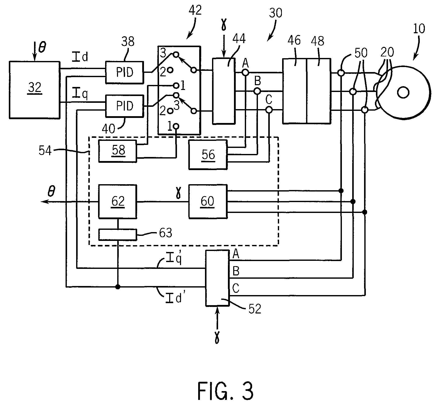
A method and apparatus for determining electrical parameters for commissioning a sensor-less permanent magnet synchronous machine uses knowledge of the rotor position to apply balanced pulses along the rotor magnet axis and perpendicular to the rotor magnet axis allowing measurement of q- and d-inductance at multiple current levels without substantial rotor movement.

Description

CROSS-REFERENCE TO RELATED APPLICATIONS[0001]—STATEMENT REGARDING FEDERALLY SPONSORED RESEARCH OR DEVELOPMENT[0002]—BACKGROUND OF THE INVENTION[0003]The present invention relates to electric motors and, in particular, to permanent magnet synchronous machines (PMSM) and, more particularly, to a method and apparatus for automatically identifying electrical parameters in sensor-less PMSMs.[0004]Permanent magnet synchronous machines are electric motors having a rotor holding a permanent magnet that may turn about an axis within a stator. The stator holds conductive coils that may be energized to create a rotating magnetic field. The rotating magnetic field is coordinated with the rotor position to draw the rotor along synchronously.[0005]Simple PMSMs employ power transistors to switch the electrical currents in the stator coils to create the necessary rotating magnetic field. “Sensor-less” PMSMs eliminate the rotor position sensors and deduce rotor position from its effect on the electr...

Claims


Application Information

Patent Timeline
Patent Type & Authority Patents(United States)
IPC IPC(8): H02P1/04
CPCH02P21/14
Inventor LIU, JINGBOHARBAUGH, MARK M.NONDAHL, THOMAS ASCHMIDT, PETER B.ROYAK, SEMYON
Owner ROCKWELL AUTOMATION TECH
Learn More