Image displaying device and method for preventing image quality deterioration

a technology of image quality and displaying device, which is applied in the field of image displaying device and image displaying method, can solve the problems of motion blur, blurring of outline, and so on, and achieve the effect of effectively preventing image quality determination of displayed images

Active Publication Date: 2012-07-24
SHARP KK
View PDF23 Cites 21 Cited by
  • Summary
  • Abstract
  • Description
  • Claims
  • Application Information

AI Technical Summary

Benefits of technology

[0060]According to the present invention, the image quality determination of displayed images may effectively be prevented by not executing the interpolation processing through motion compensation when a predetermined image tone mode determined in advance (such as the movie mode or the game mode) of a plurality of image tone modes set in the image displaying device is selected by a user.

Problems solved by technology

As compared to conventional cathode-ray tubes (CRTs) primarily used for realizing moving images, LCDs (Liquid Crystal Displays) have a drawback, so-called motion blur, which is the blurring of outline of a moving portion perceived by a viewer when displaying a moving image.
Since the impulse response of the image displaying light has a temporal spread in the above hold display mode, spatial frequency characteristics deteriorate along with temporal frequency characteristics, resulting in the motion blur.
Since the human eye can smoothly follow a moving object, if the light emission time is long as in the case of the hold type, the movement of image seems jerky and unnatural due to the time integration effect.
However, in the case of the frame interpolation processing using the linear interpolation, unnaturalness of motion (jerkiness, judder) is generated due to the frame rate conversion, and the motion blur disturbance due to the above hold display mode cannot sufficiently be improved, resulting in inadequate image quality.

Method used


Image

  • Image displaying device and method for preventing image quality deterioration
  • Image displaying device and method for preventing image quality deterioration
  • Image displaying device and method for preventing image quality deterioration

Examples


first embodiment

[0096]In the present invention, the output of the motion vector detecting portion 11e is forced to be zero vector to make the motion compensation processing of the FRC portion 10 ineffective when a predetermined image tone mode such as, for example, the movie mode or the game mode of a plurality of image tone modes set in the liquid crystal displaying device is selected by a user.

[0097]FIG. 7 is a block diagram of an exemplary main configuration of a liquid crystal displaying device according to the first embodiment of the present invention and the liquid crystal device includes the FRC portion 10, a remote control light receiving portion 13, a controlling portion 14, an image quality adjusting portion 15, a switching portion 16, a zero vector portion 17, an electrode driving portion 18, and a liquid crystal display panel 19. The switching portion 16 is disposed between the motion vector detecting portion 11e and the interpolating vector evaluating portion 11f within the FRC portion...

second embodiment

[0106]In the present invention, when a predetermined image tone mode such as, for example, movie mode or game mode of a plurality of image tone modes set in the liquid crystal displaying device is selected by a user, the interpolating vector from the interpolating vector evaluating portion 11f is set to zero-vector to make the motion compensation processing of the FRC portion 10 ineffective so that no interpolation can occur between pixels located at different positions.

[0107]FIG. 9 is a block diagram of an exemplary main configuration of a liquid crystal displaying device according to the second embodiment of the present invention and the liquid crystal displaying device includes the FRC portion 10, the remote control light receiving portion 13, the controlling portion 14, the image quality adjusting portion 15, the switching portion 16, the zero-vector portion 17, the electrode driving portion 18, and the liquid crystal display panel 19. The switching portion 16 is disposed betwee...

third embodiment

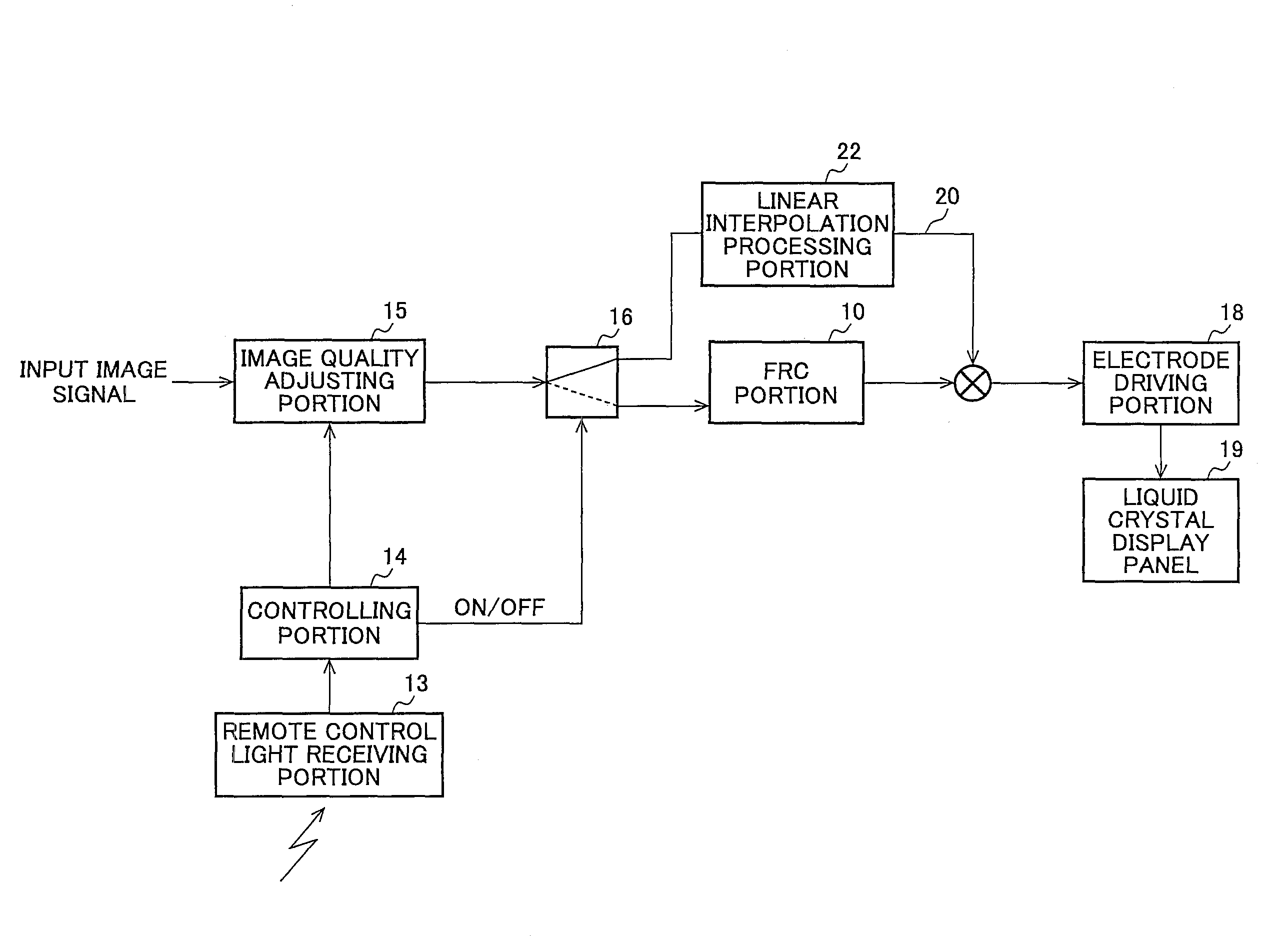
[0110]In the present invention, a path is provided to bypass the FRC portion 10 and, when a predetermined image tone mode such as, for example, movie mode or game mode of the plurality of image tone modes set in the liquid crystal displaying device is selected by a user, the input image signal is input to the bypass to change the drive frequency of the liquid crystal display panel 19 in conformity with the frame frequency of the input image signal. When a predetermined image tone mode determined in advance is selected, the switching is performed such that the input image signal is directly output and displayed on the liquid crystal display panel 19 without performing the frame rate conversion.

[0111]FIG. 10 is a block diagram of an exemplary main configuration of a liquid crystal displaying device according to the third embodiment of the present invention and the liquid crystal displaying device includes the FRC portion 10, the remote control light receiving portion 13, the controlli...


PUM


Abstract

It is an object to prevent the image quality deterioration of a moving image likely to include a plurality of the same consecutive images such as a movie video image or a CG video image due to the motion-compensated frame rate conversion (FRC) processing. An image displaying device is provided with an FRC portion (10) for converting the number of frames in an input image signal by interpolating an image signal to which a motion compensation processing has been given between the frames in the input image signal, a controlling portion (14) for controlling each portion according to an image tone mode selected by a user. The FRC portion (10) includes a motion vector detecting portion (11e) for detecting a motion vector between the frames of the input image signal, an interpolating vector evaluating portion (11f) for allocating an interpolating vector between the frames based on the motion vector information, and an interpolating frame generating portion (12d) for generating an interpolating frame from the interpolating vector. In the case that the image tone mode selected by the user is a predetermined image tone mode, the controlling portion (14) set the motion vector detected by the motion vector detecting portion (11e) to zero-vector to make the motion compensation processing of the FRC portion (10) ineffective.

Description

TECHNICAL FIELD[0001]The present invention relates to an image displaying device and method having a function of converting a frame rate or field rate, and more particularly, to an image displaying device and an image displaying method of the device, which include preventing the image quality deterioration of a moving image likely to include a plurality of the same consecutive images due to a motion-compensated rate conversion processing.BACKGROUND OF THE INVENTION[0002]As compared to conventional cathode-ray tubes (CRTs) primarily used for realizing moving images, LCDs (Liquid Crystal Displays) have a drawback, so-called motion blur, which is the blurring of outline of a moving portion perceived by a viewer when displaying a moving image. It is pointed out that this motion blur arises from the LCD display mode itself (see, e.g., Specification of Japanese Patent No. 3295437; “Ishiguro Hidekazu and Kurita Taiichiro, “Consideration on Motion Picture Quality of the Hold Type Display wi...

Claims


Application Information

Patent Timeline
Patent Type & Authority Patents(United States)
IPC IPC(8): H04N7/01
CPCG09G3/3611H04N5/142H04N5/145H04N5/165H04N5/57H04N7/0132H04N21/4318H04N21/44008H04N21/440281H04N21/4854G09G3/20G09G2320/0261G09G2320/106G09G2340/0435H04N7/0112H04N7/014
Inventor MORI, TAKESHIKOHASHIKAWA, SEIJIFURUKAWA, HIROYUKIUENO, MASAFUMIYAMAMOTO, KENICHIROHYOSHII, TAKASHI
Owner SHARP KK
Why Eureka
Try Eureka