
Prefilter, compressive coding pre-processing apparatus and decompressive decoding post-processing apparatus, and compressive coding apparatus and decompressive decoding apparatus

a compression coding and pre-processing technology, applied in the field of prefilters, can solve the problems of reducing the fineness of image quality, generating different kinds of image quality degradation, and reducing the speed of coding, so as to reduce the volume of information generation at coding of motion pictures, reduce the effect of image degradation and less effect on image degradation

Inactive Publication Date: 2006-10-26
NIPPON HOSO KYOKAI
View PDF3 Cites 11 Cited by
  • Summary
  • Abstract
  • Description
  • Claims
  • Application Information

AI Technical Summary

Benefits of technology

"The present invention provides a pre-processing apparatus for compressive coding that includes a prefilter for reducing distortion and preventing coding distortion when compressing an image. The prefilter includes a time filter for limiting the band of a moving region and a two-dimensional filter for cutting off high frequency components. The pre-processing apparatus can be used in a compressive coding apparatus for broadcasting or hi-vision transmission. Additionally, the invention provides a method for detecting and controlling the filtering operation of the prefilter based on the moving quantity or scene change of the image. The pre-processing apparatus can also include pixel skipping means and pixel space contracting means to further improve the quality of the image."

Problems solved by technology

If the image is implemented the compressive coding into such a ultra low bit rate like the above, various kinds of the image quality degradation are generated.
For example, smoothness in motion is lost due to a generation of a frame skip, reading of superimposed characters becomes difficult, and a collapse of a whole screen may take place in some case.
When the prefiltering is not implemented for an input image, since an information volume of the input image is large, a compression rate (generally, a quantization parameter) of the compressive coding apparatus becomes too large for implementing the compressive coding of the input image into an ultra low bit rate, thereby resulting in significant generation of coding degradations, such as a block distortion and a mosquito distortion.
In addition, in a region having a strong edge such as the superimposed characters, particularly, the coding degradation becomes remarkable.
As a result, recognition of the superimposed characters of a decoded image becomes difficult.
However, since the prefilter includes two filter circuits in horizontal and vertical directions, and implements processing of the band limiting two times in the horizontal and vertical directions, a high frequency region is subjected to the band limiting in the horizontal and vertical directions.
Particularly, when the image is compressively coded into a low bit rate, an edge portion of the superimposed characters becomes more unclear, and the caption is blended into the background, thereby resulting in difficulty for reading the superimposed characters in the decoded image.
Since a prefilter described in the Japanese Laid-Open Patent Publication No. 2004-297768 also removes a high frequency component, an image coding apparatus provided with the prefilter has the same problem with that of the above Japanese Patent No. 3611461.
In addition, in the image coding apparatus described in the Japanese Laid-Open Patent Publication No. 2004-297768, since a control of the prefilter is implemented using a coding parameter of a compressive coding unit, it has been impossible to control the prefilter independently of the compressive coding unit.
Therefore, a design freedom of the prefilter has been limited.
However, in a conventional compressive coding method, when the compression rate of the motion picture becomes high, a volume of information to be deleted for image compression becomes large, thereby resulting in difficulty for correctly restoring (reproducing original information as it was) the deleted information.
As a result, a significant image quality degradation may be caused in some case.
Especially, in the conventional compressive coding method, when a coded motion picture is transmitted via a narrow band (low bit rate) transmission line having a low transmission bit rate although an original information volume of the motion picture is large, a significant image quality degradation of a decoded motion picture is caused if the compression rate of the motion picture is simply increased without any countermeasures.
In addition, in a compressive coding apparatus employing the conventional compressive coding method (conventional compressive coding apparatus), when a complex motion picture is input and transmitted with a low bit rate, and when securing of a certain level of image quality is difficult, it is probable that a quantization step is set to be increased.
However, if the quantization step is increased, a block noise is generated as well as fineness of the image which forms the motion picture is lost when the image is decoded, thereby resulting in significant image quality degradation.

Method used


Image

  • Prefilter, compressive coding pre-processing apparatus and decompressive decoding post-processing apparatus, and compressive coding apparatus and decompressive decoding apparatus
  • Prefilter, compressive coding pre-processing apparatus and decompressive decoding post-processing apparatus, and compressive coding apparatus and decompressive decoding apparatus
  • Prefilter, compressive coding pre-processing apparatus and decompressive decoding post-processing apparatus, and compressive coding apparatus and decompressive decoding apparatus

Examples


first embodiment

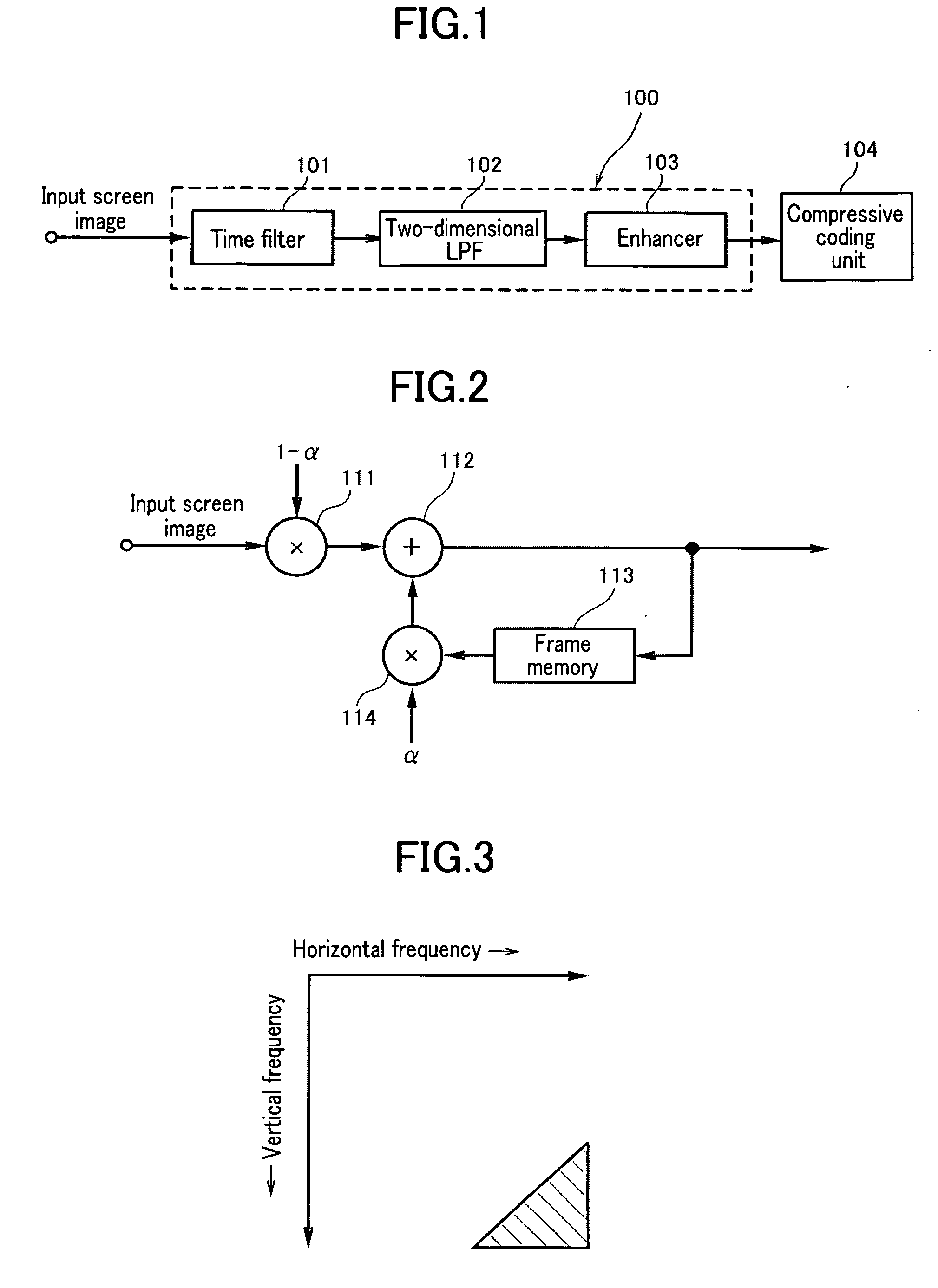
[0083]FIG. 1 is an illustration showing an example of a prefilter according to a first embodiment of the present invention. The prefilter according to the embodiment is preferably employed to a compressive coding apparatus, which includes a prefilter 100 for implementing band limiting of an input image and a compressive coding unit 104 for implementing compressive coding of a band-limited input image signal. Especially, the prefilter is suitable for the compressive coding apparatus which is used for serving a distribution of an image to a mobile terminal at a low bit rate by making use of one segment of terrestrial digital broadcasting. Here, the low bit rate, in which the present invention can be used preferably, may be fall within a range of 64 Kbps to 192 Kbps. The present invention is also effective in hi-vision transmission. In this case, an optimal range of the transmission rate is 3 Mbps to 20 Mbps for implementing the compressive coding.

[0084] The prefilter 100 according to...

second embodiment

[0098]FIG. 8 is an illustration showing a prefilter according to a second embodiment of the present invention. Meanwhile, since a time filter 201, a two-dimensional low-pass filter 202, and an enhancer 203 are identical with those of the aforementioned embodiment, explanations on them will be omitted. In the present embodiment, a moving quantity detector 204 is disposed, an input image is divided into blocks, a size of a moving quantity at each block is measured, and a strength of the time filter 201 is controlled in response to a detected moving quantity. A control of the filter strength of the time filter 201 is practiced in such a manner that, when a small movement is detected, the filter strength is increased, and when a large movement is detected, a normal filter strength is applied. Accordingly, noises are removed for a stationary image, and a strong band limiting is applied for a slow motion picture.

[0099] An example of the control where the IIR filter shown in FIG. 2 is use...

third embodiment

[0103]FIG. 10 is an illustration showing a configuration of a prefilter according to a third embodiment of the present invention. Meanwhile, in the embodiment, a two-dimensional filter 302 and an enhancer 303 are identical with those of shown in FIG. 1. In the present embodiment, a scene change detector 304 is disposed, and a time filter 301 is controlled by a control signal from the scene change detector 304. That is, when a scene change occurs in an image, the scene change detector 304 controls the time filter 301 by the control signal from the scene change detector 304 so as not to spread the effect of the time filter 301 at times before and after the scene change. For example, if the time filter 301 is configured with the IIR filter shown in FIG. 2, the feedback quantity α is equal to “0” (α=0) when the scene change happens. Meanwhile, the scene change detector can be formed with a detection method of a simple configuration by using, for example, a difference between frames.

[01...


PUM


Abstract

A prefilter for use in a compressive coding apparatus, the compressive coding apparatus including the prefilter for limiting a frequency band of an input image and a compressive coding unit for implementing compressive coding of an image signal of which frequency band is limited with the prefilter, the prefilter includes: a time filter unit; a two-dimensional filter unit; and an enhancement unit. A compressive coding pre-processing apparatus provided with the prefilter includes: a prefilter unit for attenuating a diagonal frequency component of each image; a pixel skipping unit for skipping a pixel of an image signal of which diagonal frequency component is attenuated by the prefilter unit by folding back a horizontal high frequency component to a vertical high frequency component, or folding back the vertical high frequency component to the horizontal high frequency component; and a pixel space contracting unit for contracting a space of the skipped pixel.

Description

CROSS REFERENCE TO RELATED APPLICATIONS [0001] This application claims the foreign priority benefit under Title 35, United States Code, §119(a)-(d) of Japanese Patent Applications No. 2005-127637 and 2005-180983, filed on Apr. 26, 2005 and Jun. 21, 2005, respectively, the contents of which are hereby incorporated by reference. BACKGROUND OF THE INVENTION [0002] 1. Field of the Invention [0003] The present invention relates to a prefilter used for a compressive coding apparatus, and more particularly, relates to a prefilter suitable for the compressive coding apparatus which implements compressive coding of an input image into a low bit rate, and also relates to a compressive coding pre-processing apparatus for processing a motion picture before the compressive coding and a decompressive decoding post-processing apparatus for processing the motion picture after decompressive decoding, and a compressive coding apparatus provided with the compressive coding pre-processing apparatus and...

Claims


Application Information

Patent Timeline
Patent Type & Authority Applications(United States)
IPC IPC(8): H04B1/66H04N11/02H04N11/04H04N7/12
CPCH04N19/85H04N19/80
Inventor IGUCHI, KAZUHISAGOHSHI, SEIICHISAKAIDA, SHINICHI
Owner NIPPON HOSO KYOKAI
Learn More