Variable focal length lens system and image pickup device

Inactive Publication Date: 2012-07-24
SONY CORP
View PDF5 Cites 4 Cited by
  • Summary
  • Abstract
  • Description
  • Claims
  • Application Information

AI Technical Summary

Benefits of technology

[0018]Specifically, the variable power ratio of the variable focal length lens system can be heightened without increasing total optical length by strengthening the refractive power of each lens group. However, when the refractive power of each lens group is strengthened, variation in various aberrations which variation occurs at a time of change in focal length may not be corrected. Thus, when a high variable power ratio is to be secured by strengthening the refractive power of each lens group, predetermined optical performance may not be obtained. Consequently, to secure a high variable power ratio and obtain predetermined optical performance as well, it is difficult to avoid a size increase.
[0072]In addition, the image pickup device according to the above-described embodiment of the present invention can achieve much higher performance by a variable focal length lens system that achieves both a much higher variable power ratio and a much smaller size than the related art.

Problems solved by technology

However, when a variable power ratio exceeding 20 times is to be secured in the variable focal length lens system of the four-group configuration of a positive group, a negative group, a positive group, and a positive group, it is difficult to achieve sufficient miniaturization.
However, when the refractive power of each lens group is strengthened, variation in various aberrations which variation occurs at a time of change in focal length may not be corrected.
Thus, when a high variable power ratio is to be secured by strengthening the refractive power of each lens group, predetermined optical performance may not be obtained.
Consequently, to secure a high variable power ratio and obtain predetermined optical performance as well, it is difficult to avoid a size increase.
It is therefore difficult to achieve both even higher variable power and smaller size.

Method used


Image

  • Variable focal length lens system and image pickup device
  • Variable focal length lens system and image pickup device
  • Variable focal length lens system and image pickup device

Examples


first embodiment

First Numerical Example

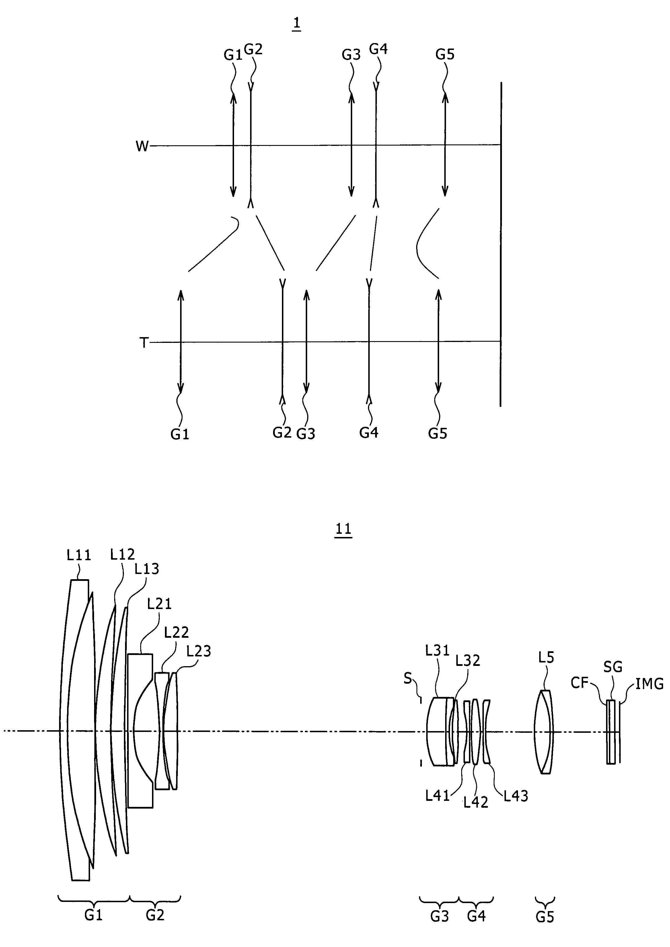
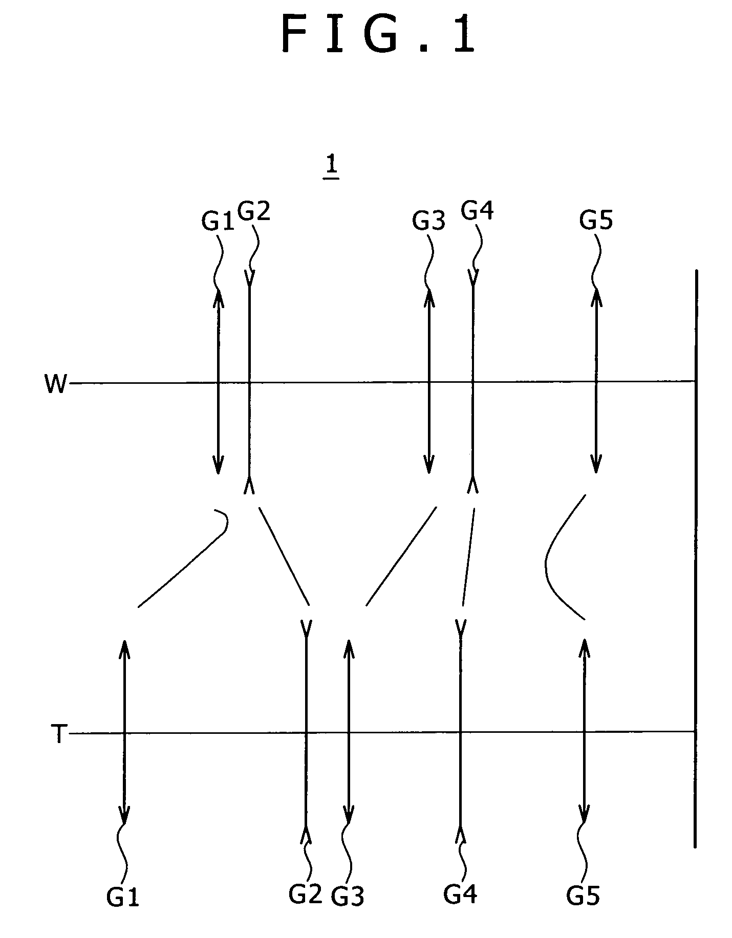
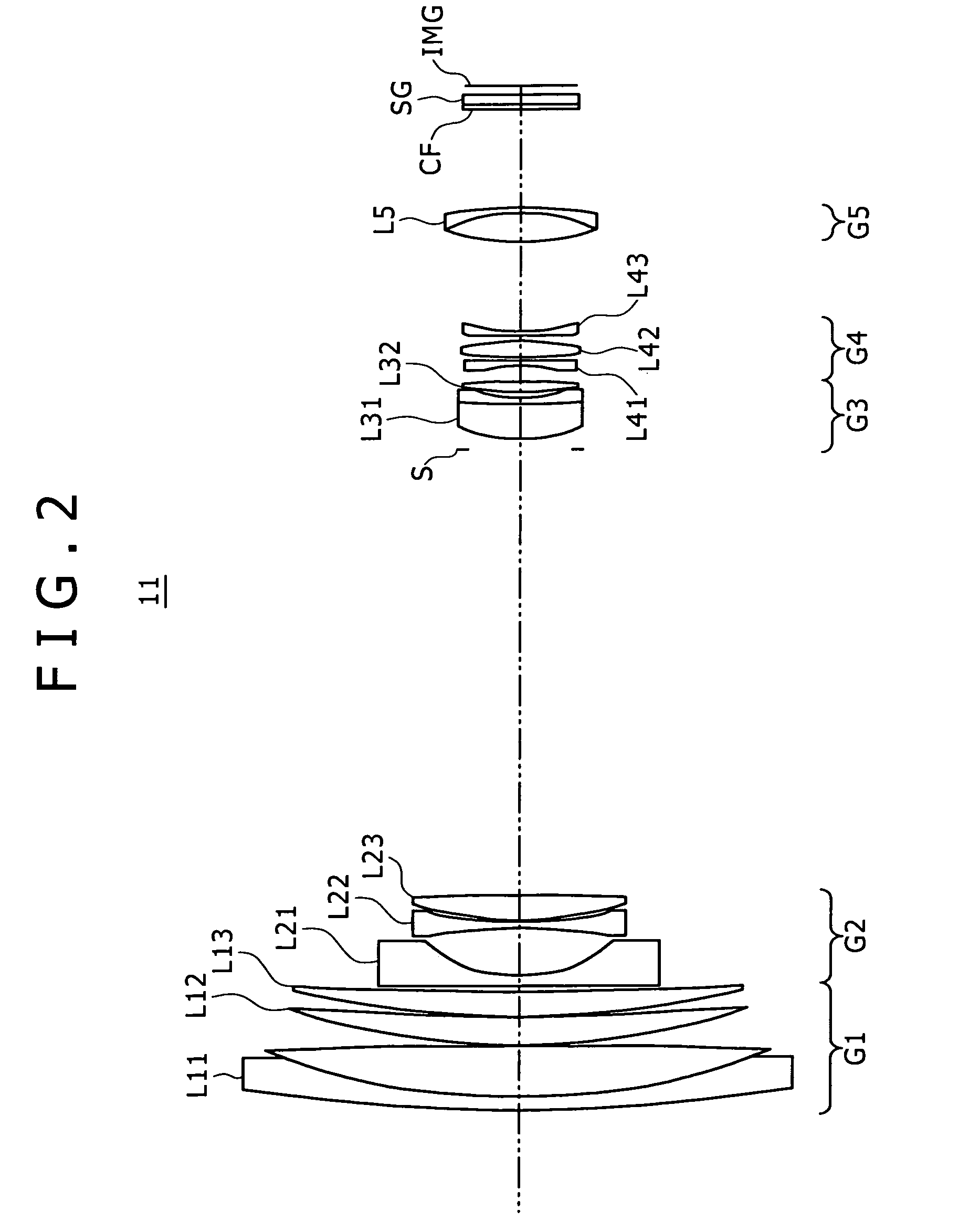
[0200]FIG. 2 shows a variable focal length lens system 11 in a first numerical example, the variable focal length lens system 11 being formed by, in order from an object side, a first lens group G1 having positive refractive power, a second lens group G2 having negative refractive power, a third lens group G3 having positive refractive power, a fourth lens group G4 having negative refractive power, and a fifth lens group G5 having positive refractive power.

[0201]In this variable focal length lens system 11, the first lens group G1 is formed by a cemented lens L11 of a negative lens of a meniscus shape having a convex surface facing the object side and a positive lens having a convex surface facing the object side, a positive lens L12 of a meniscus shape having a convex surface facing the object side, and a positive lens L13 of a meniscus shape having a convex surface facing the object side.

[0202]The second lens group G2 is formed by a negative lens L21 having ...

second embodiment

Second Numerical Example

[0218]FIG. 8 shows a variable focal length lens system 12 in a second numerical example, the variable focal length lens system 12 being formed by, in order from an object side, a first lens group G1 having positive refractive power, a second lens group G2 having negative refractive power, a third lens group G3 having positive refractive power, a fourth lens group G4 having negative refractive power, and a fifth lens group G5 having positive refractive power.

[0219]In this variable focal length lens system 12, the first lens group G1 is formed by a cemented lens L11 of a negative lens of a meniscus shape having a convex surface facing the object side and a positive lens having a convex surface facing the object side, a positive lens L12 of a meniscus shape having a convex surface facing the object side, and a positive lens L13 of a meniscus shape having a convex surface facing the object side.

[0220]The second lens group G2 is formed by a negative lens L21 havin...

third embodiment

Third Numerical Example

[0236]FIG. 14 shows a variable focal length lens system 13 in a third numerical example, the variable focal length lens system 13 being formed by, in order from an object side, a first lens group G1 having positive refractive power, a second lens group G2 having negative refractive power, a third lens group G3 having positive refractive power, a fourth lens group G4 having negative refractive power, and a fifth lens group G5 having positive refractive power.

[0237]In this variable focal length lens system 13, the first lens group G1 is formed by a cemented lens L11 of a negative lens of a meniscus shape having a convex surface facing the object side and a positive lens having a convex surface facing the object side, a positive lens L12 of a meniscus shape having a convex surface facing the object side, and a positive lens L13 of a meniscus shape having a convex surface facing the object side.

[0238]The second lens group G2 is formed by a negative lens L21 having...


PUM


Abstract

Disclosed herein is a variable focal length lens system including a first lens group, a second lens group, a third lens group, a fourth lens group, and a fifth lens group. The first to the fifth lens groups are arranged in order from an object side. The variable focal length lens system satisfies following conditional expressions (1) to (3):0.95<f13T / ft<1.4  (1)0.08<f2 / f4<0.3  (2)0.06<Δ3 / ft<0.22  (3)where f13T is combined focal length of the first to third lens groups in the telephoto end state, ft is focal length of the lens system as a whole in the telephoto end state, f2 is focal length of the second lens group, f4 is focal length of the fourth lens group, and Δ3 is an amount of travel of the third lens group from the wide-angle end state to the telephoto end state.

Description

BACKGROUND OF THE INVENTION[0001]1. Field of the Invention[0002]The present invention relates to a variable focal length lens system and an image pickup device, and particularly to the technical field of a variable focal length lens system and an image pickup device that are used in a video camera, a digital still camera and the like, whose angle of view in a wide-angle end state exceeds 74 degrees, and whose variable power ratio exceeds 30 times.[0003]2. Description of the Related Art[0004]In the past, a method that converts an amount of light of a subject image formed on an image pickup element surface into electric output by an image pickup element using a photoelectric conversion element such as a CCD (Charge Coupled Device), a CMOS (Complementary Metal Oxide Semiconductor) or the like, and which records the electric output is known as recording means in a camera.[0005]With the recent progress of microfabrication techniques, central processing units (CPU) have been increased in ...

Claims


Application Information

Patent Timeline
IPC IPC(8): G02B9/60
CPCG02B13/18G02B15/173G02B15/145121
Inventor OHTAKE, MOTOYUKIMURATA, MASAYUKIKIKUCHI, ATSUO
Owner SONY CORP
Why Eureka
Try Eureka