Zoom lens for projection and projection display device
a technology of zoom lens and projection display device, which is applied in the field of zoom lens for projection, can solve the problems of increasing manufacturing cost, and achieve the effects of wide angle of view, reduced cost, and high variable power ratio
- Summary
- Abstract
- Description
- Claims
- Application Information
AI Technical Summary
Benefits of technology
Problems solved by technology
Method used
Image
Examples
example 1
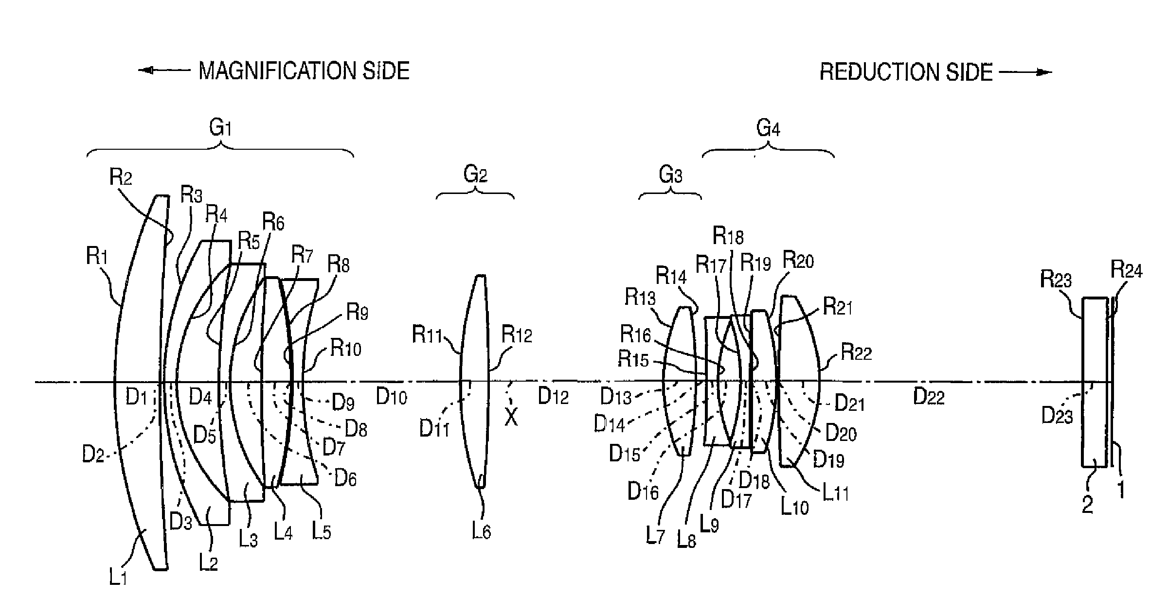
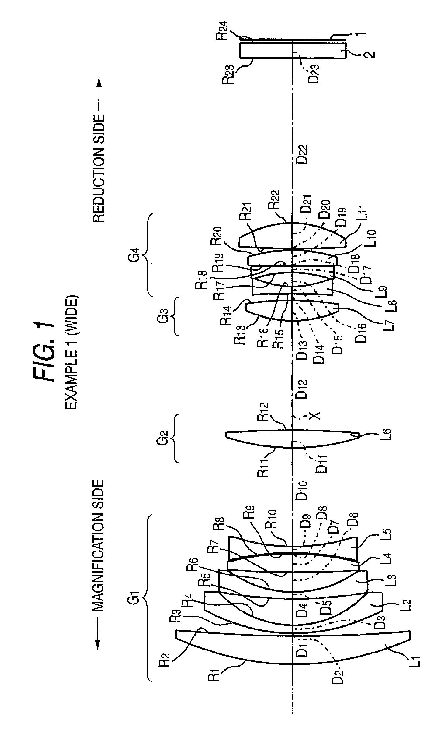
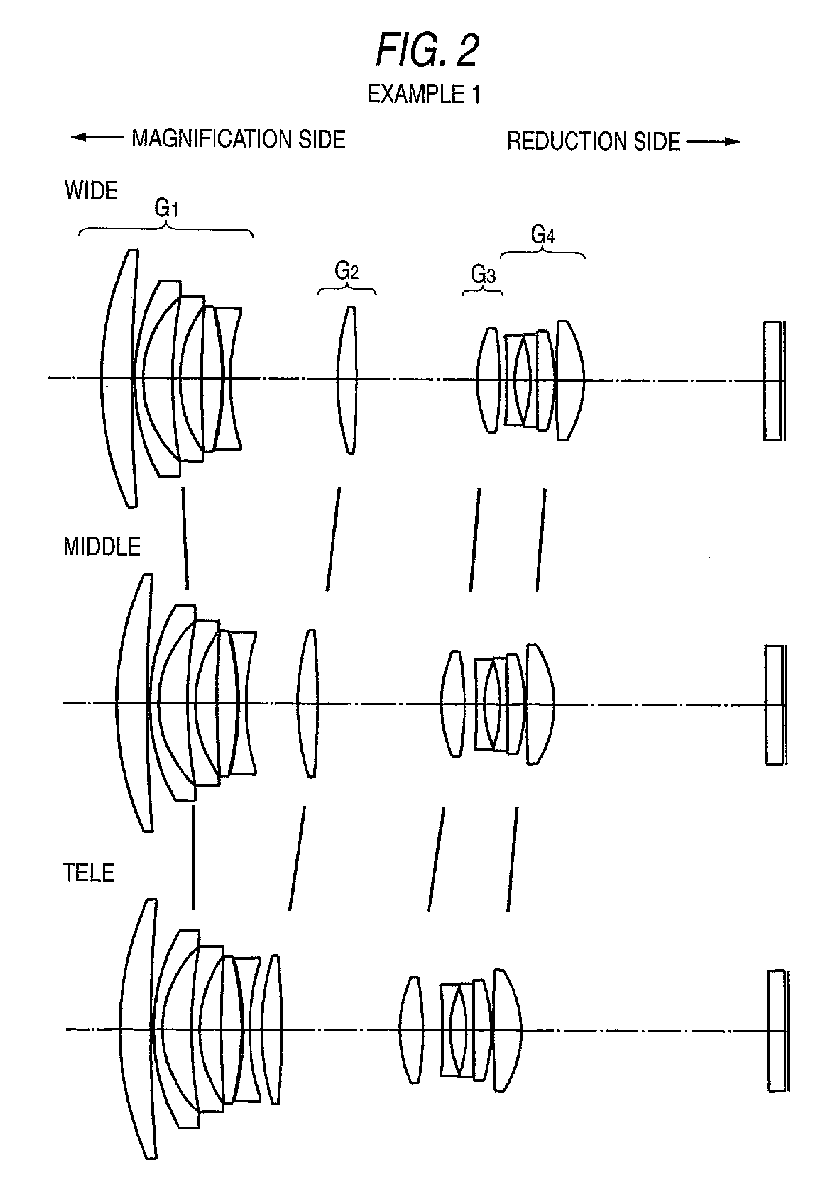
[0104]A schematic constitution of the zoom lens for projection (wide angle end) according to an example 1 is shown in FIG. 1. This zoom lens for projection includes a first lens group G1 having a negative refractive power, a second lens group G2 having a positive refractive power, a third lens group G3 having a positive refractive power, and a fourth lens group G4 having a positive or negative refractive power in order from the magnification side. At variable power from the wide-angle end to the telephoto end, the second lens group G2, the third lens group G3 and the fourth lens group G4 are moved to the magnification side, and at its latter stage, a cover glass (filter part) 2 and a DMD 1 are disposed. In the figure, X denotes an optical axis.
[0105]Herein, the first lens group G1 has a first lens L1 of a positive meniscus lens with a convex surface on the magnification side, a second lens L2 and a third lens L3 each having a negative meniscus lens with a convex surface on the magni...
example 2
[0114]A schematic constitution of the zoom lens for projection according to an example 2 is shown in FIG. 3. The lens constitution of the zoom lens for projection according to the example 2 is almost the same as the example 1, and the duplicate explanation is omitted.
[0115]Table 3 shows the values of the zoom lens for projection, including the radius of curvature R (mm) of each lens face, the on-axis surface spacing D (mm) of each lens, the refractive index N of each lens at the d-line, and the Abbe number ν.
[0116]Also, the faces (fifteenth face and sixteenth face) of the eighth lens L8 are aspheric. Table 4 shows the constant K and the values of A3 to A20 in the above aspheric expression for each aspheric surface.
TABLE 3f = 16.75~21.17~26.72Bfw = 36.01FNo = 2.20~2.50~2.852ω = 67.0°~55.2°~44.8°SurfaceNumberRDNdνd 155.7366.031.5168064.2 2295.7940.50 336.7141.611.7725049.6 420.4875.48 596.6941.401.8340037.2 623.0194.28 7685.3973.681.8466623.8 8−47.4570.20 9−43.7521.301.5638460.71041.0...
example 3
[0122]A schematic constitution of the zoom lens for projection according to an example 3 is shown in FIG. 5. The lens constitution of the zoom lens for projection according to the example 3 is almost the same as the example 1, and the duplicate explanation is omitted.
[0123]Table 5 shows the values of the zoom lens for projection, including the radius of curvature R (mm) of each lens face, the on-axis surface spacing D (mm) of each lens, the refractive index N of each lens at the d-line, and the Abbe number ν.
[0124]Also, the faces (fifteenth face and sixteenth face) of the eighth lens L8 are aspheric. Table 6 shows the constant K and the values of A3 to A20 in the above aspheric expression for each aspheric surface.
TABLE 5f = 16.75~21.16~26.72Bfw = 36.01FNo = 2.20~2.49~2.822ω = 67.2°~55.2°~44.8°SurfaceNumberRDNdνd 158.2425.601.5168064.2 2261.2740.50 337.4781.611.7550052.3 420.3465.25 583.6311.401.8340037.2 623.4663.89 7217.2033.741.8466623.8 8−53.1200.22 9−52.7601.301.6779055.31043.2...
PUM
 Abstract
Description
Claims
Application Information
 - R&D
- Intellectual Property
- Life Sciences
- Materials
- Tech Scout
- Unparalleled Data Quality
- Higher Quality Content
- 60% Fewer Hallucinations
Browse by: Latest US Patents, China's latest patents, Technical Efficacy Thesaurus, Application Domain, Technology Topic, Popular Technical Reports.
© 2025 PatSnap. All rights reserved.Legal|Privacy policy|Modern Slavery Act Transparency Statement|Sitemap|About US| Contact US: help@patsnap.com


