
Lens barrel and imaging apparatus

一种镜筒、镜头的技术,应用在可折叠结构的镜筒领域,能够解决光量不足、不能到达等问题

Inactive Publication Date: 2011-06-29
SONY CORP
View PDF7 Cites 18 Cited by
  • Summary
  • Abstract
  • Description
  • Claims
  • Application Information

AI Technical Summary

Problems solved by technology

[0006] The luminous flux directed to the part between adjacent photoelectric conversion elements when there is no microlens array is guided to these photoelectric conversion elements through the microlens array, but the microlens array restricts the position of the exit pupil of the lens system (from the image plane distance to exit pupil)
[0007] The reason is that when the exit pupil position of the lens system is close to the photoelectric conversion elements, that is, when the chief ray reaching each of the photoelectric conversion elements forms a large angle with the optical axis of the lens system, the off-axis light flux directed to the outer periphery of the screen is large. The angle is inclined to the optical axis and thus cannot reach the photoelectric conversion element at the periphery, resulting in insufficient light quantity

Method used


Image

  • Lens barrel and imaging apparatus
  • Lens barrel and imaging apparatus
  • Lens barrel and imaging apparatus

Examples


no. 1 example

[0072] 2. Numerical examples corresponding to the first embodiment (first and second numerical examples)

no. 2 example

[0074] 4. Numerical example corresponding to the second embodiment (third numerical example)

[0075] 5. Configuration of imaging device and digital camera

[0076] 6. Other embodiments.

[0077]

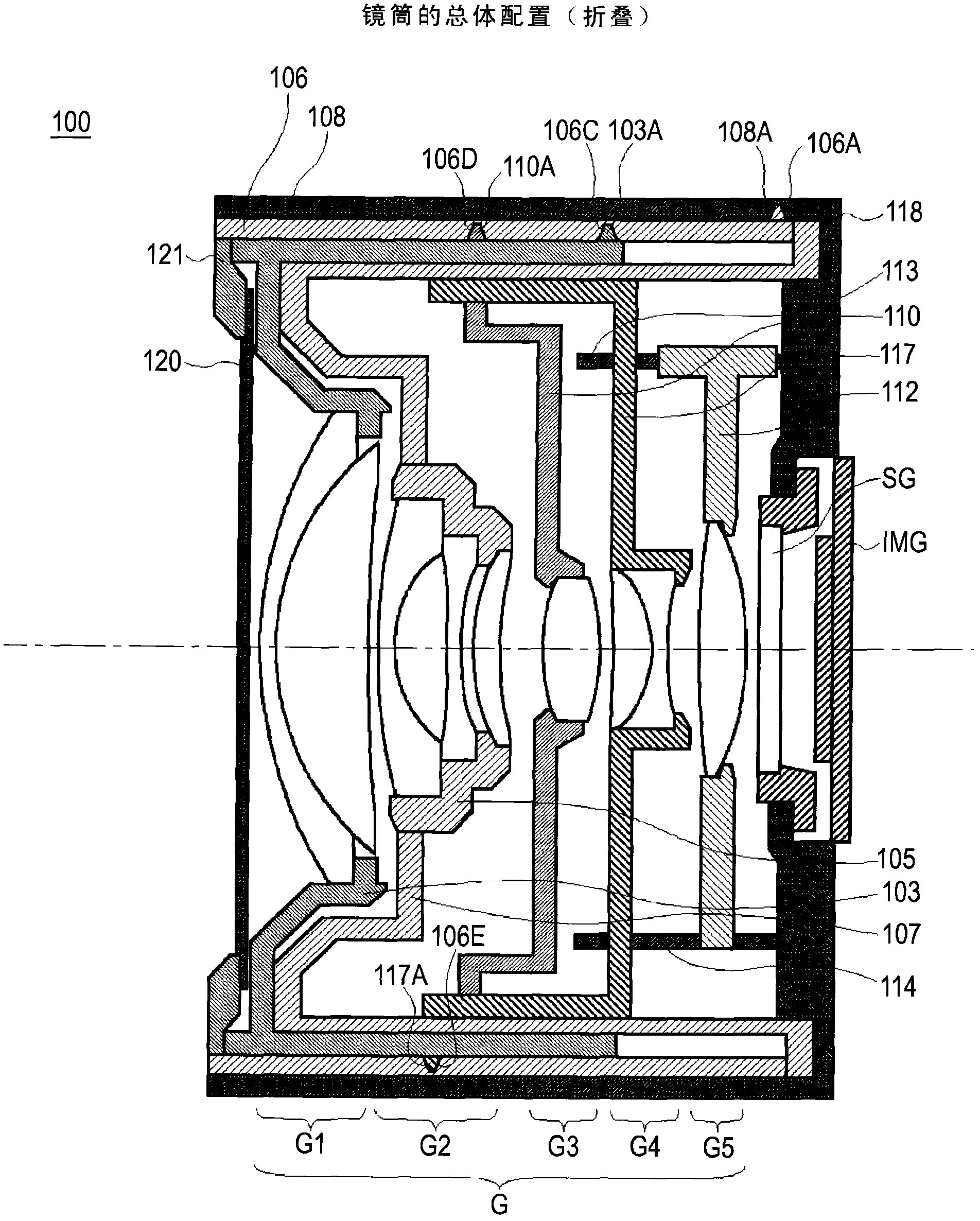
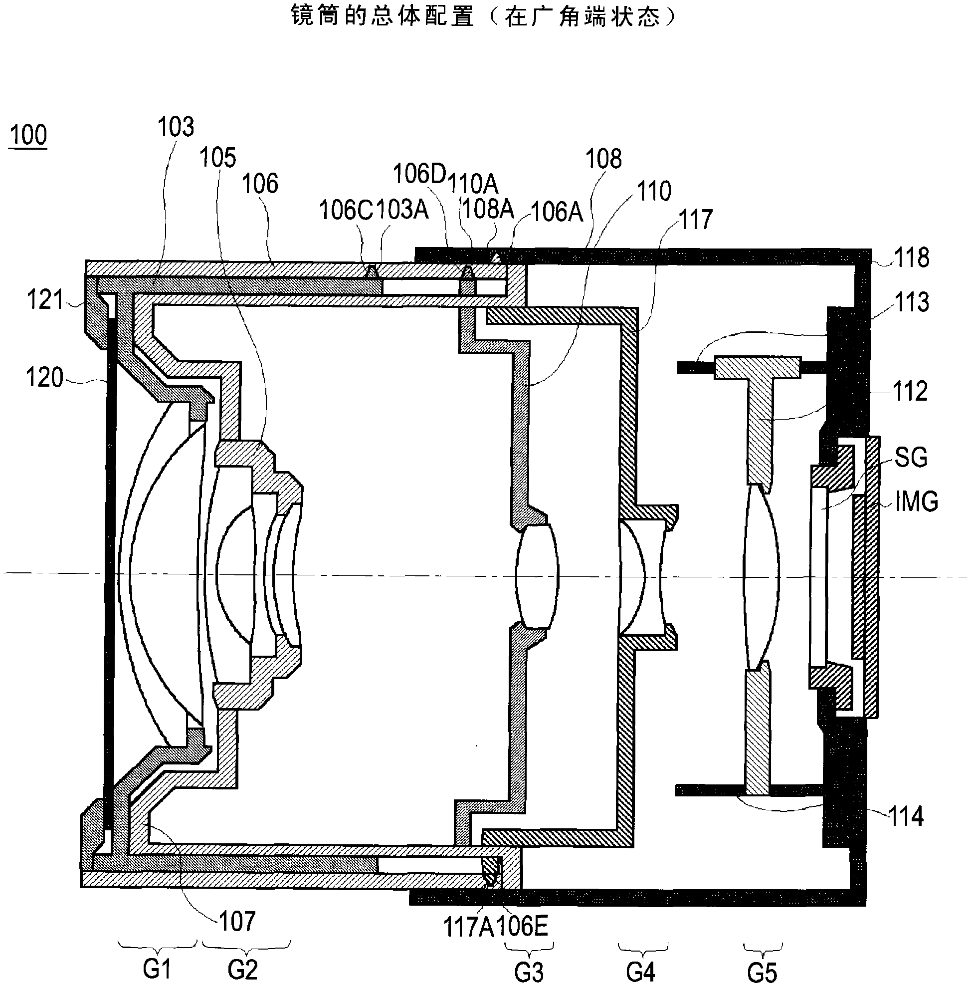
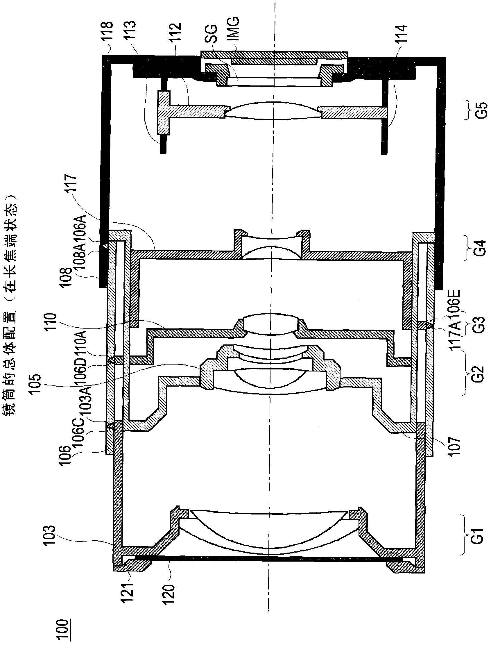
[0078] [1-1. Arrangement of Lens Barrel]

[0079] The lens barrel in the first embodiment includes a variable focal length lens system having at least three movable lens groups and a driving mechanism as a guide for making the movable lens groups constituting the variable focal length lens system Each group moves forward and backward in the direction of the optical axis.

[0080] In the following description, a lens system in which the focal point changes with the focal length is called a variable focal length lens system, where the focal point is where the image is brought into focus. On the other hand, as a lens system whose focal point does not vary with the focal length, a zoom lens is considered a type of variable focal length lens system.

[0081] First, the configuratio...


PUM


Abstract

The present invention relates to a lens barrel and an imaging apparatus. The lens barrel includes: a variable focal length lens system including at least three movable lens groups; and guiding means for moving the variable focal length lens system forward and backward in an optical axis direction. The variable focal length lens system includes at least first, second and third lens groups having positive, negative and positive refracting power respectively, arranged in this order begin from an object side. When a lens position setting is changed from a wide angle end state to a telescopic end state, at least the first and third lens groups are moved toward the object side such that air separation between the first and second lens groups monotonously increases and air separation between the second and third lens groups monotonously decreases. The guiding means includes a fixed frame, a rotating frame, a rectilinear guiding frame, a first guide frame, and a second guide frame.

Description

technical field [0001] The present invention relates to a lens barrel and an imaging device, and particularly relates to a lens barrel employing a so-called foldable structure. Background technique [0002] As a recording method in a digital camera, there is a known method in which an imaging device composed of a photoelectric conversion element such as a CCD sensor and a CMOS sensor converts the amount of light forming an object image on the surface of the imaging device into an electrical output, This electrical output is then recorded. [0003] With the development of micro-processing technology in recent years, CPUs (Central Processing Units) have operated faster and storage media have increased their storage density, so that a large amount of image data that could not be processed before can now be processed at high speed. [0004] Light-receiving devices have also increased in storage density and shrunk in size. Higher storage densities allow higher spatial frequency...

Claims


Application Information

Patent Timeline
Patent Type & Authority Applications(China)
IPC IPC(8): G02B7/10G03B17/04H04N5/225
CPCG02B15/173G03B17/04G02B7/102G02B15/145121
Inventor 大竹基之
Owner SONY CORP
Learn More