Method for simulating the behavior of a bonded joint of two parts

a technology of bonded joints and composite materials, applied in the field of simulating the behavior of bonded joints of two parts, can solve the problems of not allowing parametric analysis, complex and expensive, and not (simply) contemplating two, and achieve the effect of facilitating the determination of failure criteria

a technology of bonded joints and composite materials, applied in the field of simulating the behavior of bonded joints of two parts, can solve the problems of not allowing parametric analysis, complex and expensive, and not (simply) contemplating two, and achieve the effect of facilitating the determination of failure criteria

US8229717B2Inactive Publication Date: 2012-07-24AIRBUS OPERATIONS SL

Image

  • Method for simulating the behavior of a bonded joint of two parts
  • Method for simulating the behavior of a bonded joint of two parts
  • Method for simulating the behavior of a bonded joint of two parts

Examples


Embodiment Construction

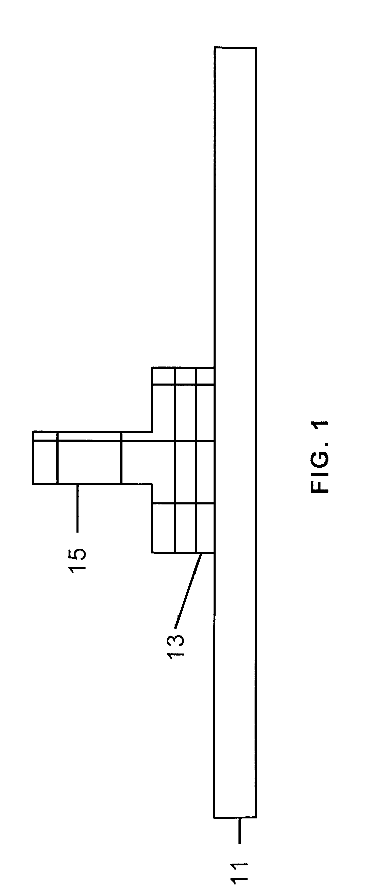
[0036]Bonded joints such as that shown in FIG. 1, in which the stiffening elements 15 is joined to the panel 11 by means of an adhesive layer 13, are frequently used in the stiffened panels used in aeronautical structures.

[0037]The problem of these types of bonded joints is a problem with the following basic characteristics:[0038]It is a two-dimensional problem which can have a complex geometry.[0039]The stress condition in the three-dimensional adhesive body comprises tensile (or peel) stresses and shear stresses.[0040]Large displacements due to buckling phenomena or large rotations of the adhesive layer due to load eccentricities can occur.[0041]The adhesive has a plastic behavior under shearing.

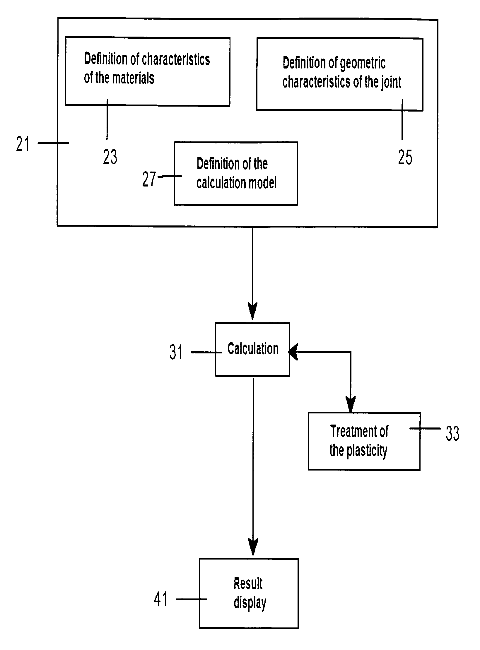
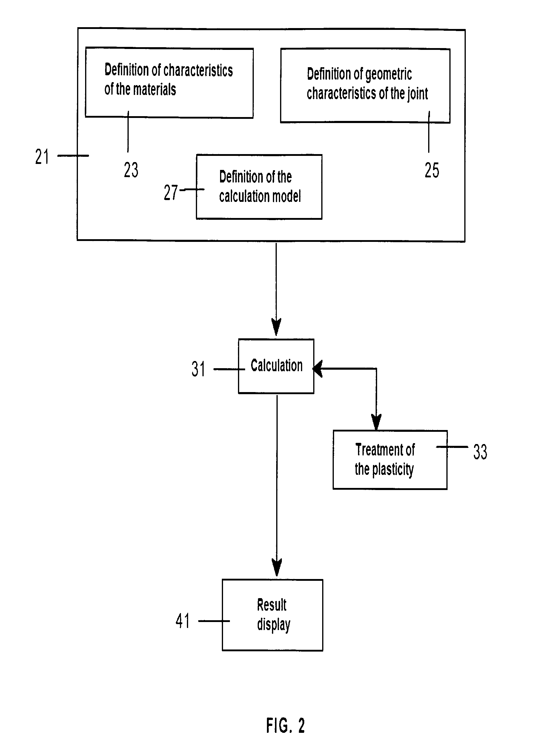
[0042]An embodiment of the method of the present invention is described in detail below, comprising the following three main steps:[0043]Preparation step 21, including a sub-step 23 of defining the characteristics of the materials of the bonded joint, a sub-step 25 of defining the geometri...


PUM


Abstract

A method for simulating the behavior of a bonded joint of two composite material parts with an adhesive material layer. The method includes the steps of a) providing a Finite Element Model with all the relevant information for analyzing the structural joint; b) providing a calculation model for calculating the deformations of the adhesive material layer when it is subjected to tensile / peel and shear stresses, including a plastic behavior of the adhesive of a linear type under tension / peeling and of a non-linear type under shearing; and c) simulating the behavior of the bonded joint by applying the calculation model to obtain the failure indices of each failure mode. A system which is useful as an aid in the design of the structural joint using a computer-implemented Finite Element Model of the structural joint.

Description

FIELD OF THE INVENTION[0001]The present invention relates to a method for simulating the behavior of a joint of two parts bonded by means of an adhesive layer and more particularly, to the joint of two composite material parts, such as a planar panel and a stiffening element, used in aeronautical structures.BACKGROUND OF THE INVENTION[0002]The use of composite materials in the design of aeronautical structures began timidly after World War II. The first materials, basically glass fibers embedded in polyester resins were used in the design of secondary structure elements, such as radomes, protection of antennas and hulls. The constant evolution of the developments of new materials has led to the progressive use thereof in more airplane components.[0003]Twenty-five years of accelerated evolution, both of the properties of the materials and the knowledge of their behavior, have passed since the milestone of the certification of the first primary structure element of a passenger airplan...

Claims


Application Information

Patent Timeline
24 Jul 2012
Publication
US8229717B2
IPC
G06G7/48
CPC
G06F17/5018; G06F2217/44; G06F2113/26; G06F30/23
Inventors
RIVEIRA RODRIGUEZ, IGNACIO; DE LA GANDARA VERANO, JUAN LUIS