Liquid ejection head and method for manufacturing liquid ejection head

a technology of liquid ejection and liquid ejection, which is applied in the direction of printing, inking apparatus, etc., can solve the problems of reducing the landing accuracy of ejection droplets, affecting the accuracy of electric circuits, and degrading the quality of output images, so as to improve the landing accuracy of droplets and reduce distance

Inactive Publication Date: 2012-07-31
CANON KK
View PDF8 Cites 2 Cited by
  • Summary
  • Abstract
  • Description
  • Claims
  • Application Information

AI Technical Summary

Benefits of technology

[0010]The present invention is directed to a liquid ejection head which enables a reduction in the distance between a print medium and an ejection port formation face of the liquid ejection head on which an ejection port is formed, improving the landing accuracy of droplets ejected from the liquid ejection head.
[0012]The liquid ejection head according to the present invention allows the connection wiring to be formed of a small amount of conductive material. This enables a reduction in the amount by which the electric connection portion of the liquid ejection head projects in the droplet ejection direction. Thus, the ejection port formation face of the liquid ejection head can be located close to the print medium. Therefore, the landing accuracy of droplets ejected from the liquid ejection head can be improved.
[0014]Furthermore, with the method for manufacturing the liquid ejection head according to the present invention, in the connection wiring forming step, the connection wiring is placed so as to be supported by the support portion placed with the element substrate in the step of placing the element substrate. The connection wiring thus is required only a little strength. Consequently, the connection wiring is formed thinner. This enables a reduction in the amount by which the electric connection portion of the liquid ejection head projects in the droplet ejection direction. As a result, the ejection port formation face of the liquid ejection head can be located close to the print medium.

Problems solved by technology

For these printing apparatuses, one of a major factor affecting the quality of output images printed on print media is the landing accuracy of droplets.
When the printing apparatus is used to print circuits in manufacturing electric circuits, the landing accuracy also affects the accuracy of the electric circuits.
The increased distance between the ejection port formation face of the liquid ejection head and the print medium may reduce the landing accuracy of ejected droplets.
This may in turn degrade the quality of output images.
In such a case, a surface of the print medium may be damaged, also degrading the quality of output images.
If the liquid ejection head is used to print circuits in manufacturing electric circuits, the degraded quality of output images may affect the electrical characteristics of the electric circuits.
The increased distance between the liquid ejection head and the print medium correspondingly reduces the landing accuracy of ejected droplets.

Method used


Image

  • Liquid ejection head and method for manufacturing liquid ejection head
  • Liquid ejection head and method for manufacturing liquid ejection head
  • Liquid ejection head and method for manufacturing liquid ejection head

Examples


Embodiment Construction

[0019]Embodiments of the present invention will be described below with reference to the accompanying drawings.

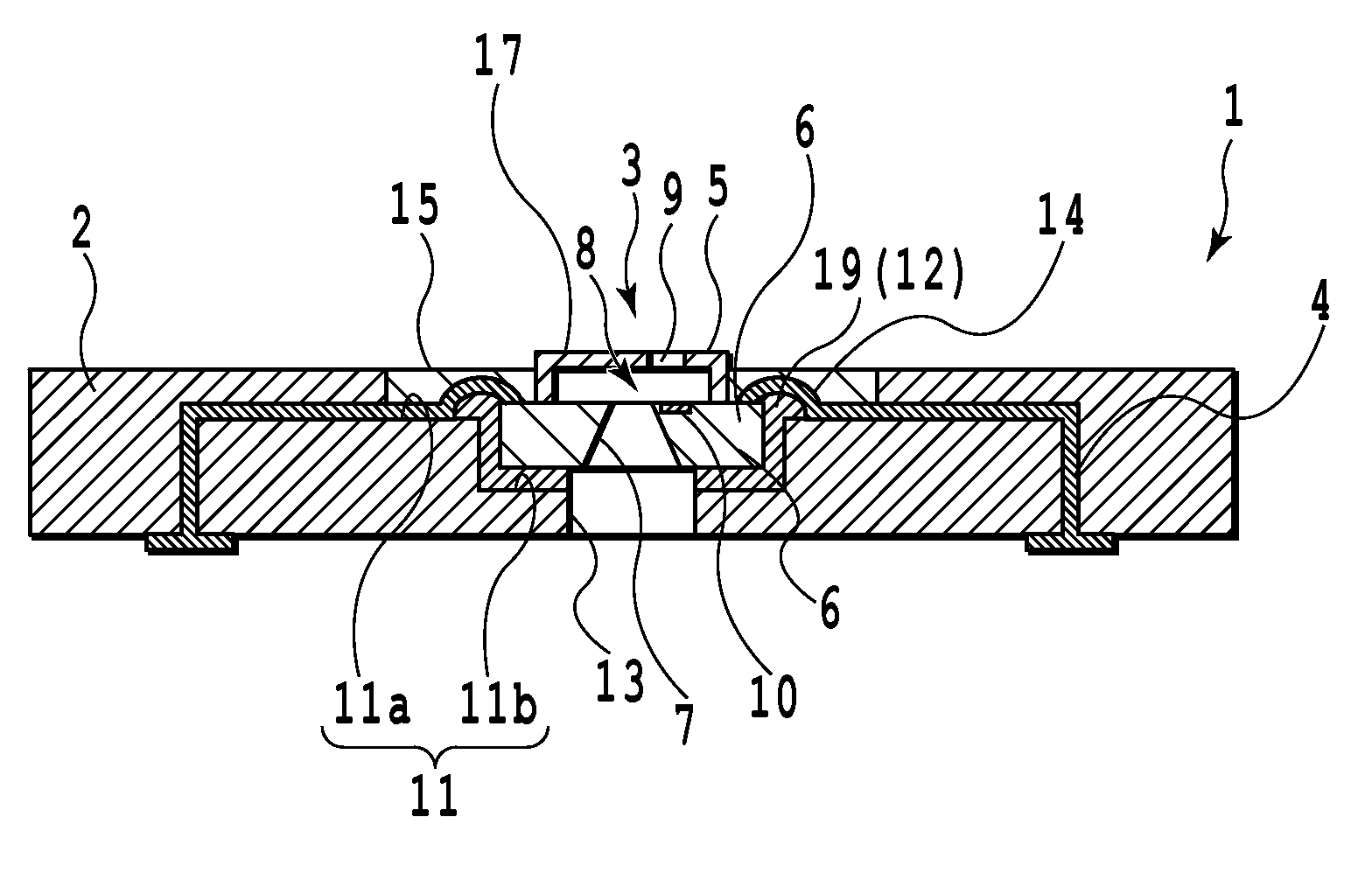
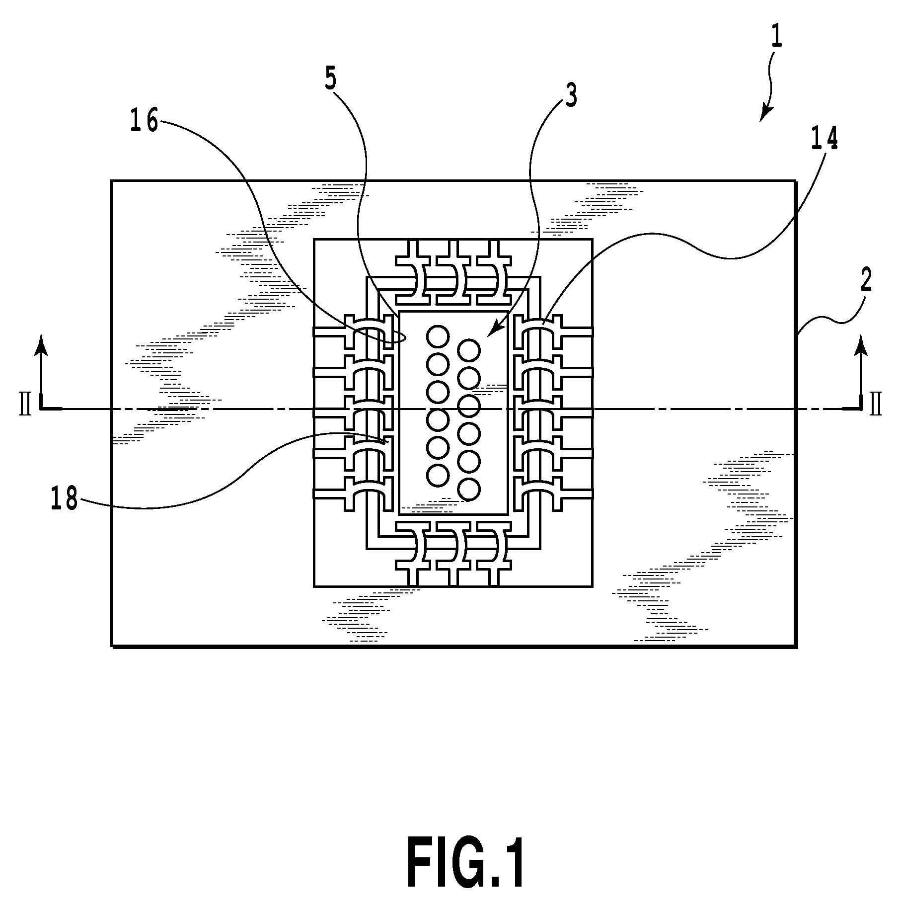
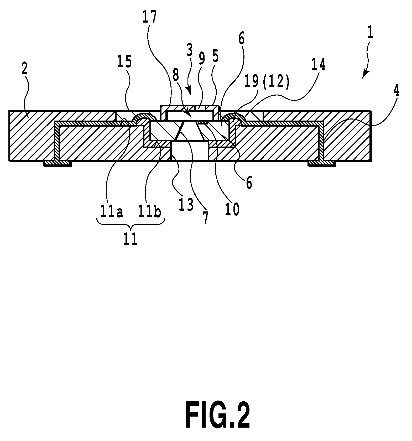
[0020]FIG. 1 is a plan view of a print head 1 as a liquid ejection head according to the present invention. FIG. 2 is a sectional view of the print head 1 taken along line II-II in FIG. 1. The print head 1, used in the present embodiment, functions as an ink jet print head used for an ink jet printing apparatus ejecting ink onto a print medium.

[0021]The print head 1, shown in FIGS. 1 and 2, has a supporting member 2 and an element substrate 3. The supporting member 2 has wiring inside of the supporting member 4 formed therein and through which electricity is transmitted. In the present embodiment, the wiring inside of the supporting member 4 is embedded in the supporting member 2. Consequently, the supporting member 2, formed of an insulating material, prevents electricity passing through the wiring inside of the supporting member 4 from flowing through the other parts.

[002...


PUM


Abstract

The present invention provides liquid ejection head enables a reduction in the distance between a print medium and an ejection port formation face of the liquid ejection head on which an ejection port is formed, improving the landing accuracy of droplets ejected from the liquid ejection head. A print head according to the present invention includes an element substrate and a supporting member. A supporting portion is located in the space between the element substrate and the supporting member. Connection wiring is formed on the supporting portion. The connection wiring is provided which connects wiring inside of the supporting member provided in the supporting member to the heat generating element.

Description

BACKGROUND OF THE INVENTION[0001]1. Field of the Invention[0002]The present invention relates to a liquid ejection head having an ejection energy generating element that generates and applies energy to a liquid to eject the liquid through an ejection port, as well as a method for manufacturing such a liquid ejection head.[0003]2. Description of the Related Art[0004]Printing apparatuses using a liquid ejection head to eject droplets intrinsically eject droplets onto a print medium such as paper in a non-contact manner to attach the droplets to the print medium for printing. However, recent printing apparatuses using a liquid ejection head have more frequently been applied to print media other than paper. These printing apparatus have been used for printing on fibers, that is, textile printing, printing of circuits for manufacturing electric circuits, printing on glass substrates, or the like. For these printing apparatuses, one of a major factor affecting the quality of output images...

Claims


Application Information

Patent Timeline
Patent Type & Authority Patents(United States)
IPC IPC(8): B41J2/05B41J2/14B41J2/16
CPCB41J2/14024B41J2/14072B41J2202/11B41J2/01B41J2/045B41J2/1433B41J2/16
Inventor JINDAI, KAZUHIROTSURUOKA, YUJIMORI, TAKASHIYAMAGUCHI, NOBUHITOFURUKAWA, MASAOKAMIYA, SEIICHI
Owner CANON KK
Why Eureka
Try Eureka