Microelectromechanical (MEM) thermal actuator

Active Publication Date: 2012-07-31
NAT TECH & ENG SOLUTIONS OF SANDIA LLC
View PDF43 Cites 16 Cited by
  • Summary
  • Abstract
  • Description
  • Claims
  • Application Information

AI Technical Summary

Problems solved by technology

Heating the beam, for example by passing an electrical current through it, causes the beam to expand and eventually buckle.
An issue for buckling beam thermal actuators is controlling (i.e. const

Method used


Image

  • Microelectromechanical (MEM) thermal actuator
  • Microelectromechanical (MEM) thermal actuator
  • Microelectromechanical (MEM) thermal actuator

Examples


Embodiment Construction

[0028]The following examples describe embodiments of the invention as can be fabricated in a surface micromachining technology such as the Sandia Ultra-planar Multi-level MEMS Technology (SUMMiT™) available at Sandia National Laboratories, Albuquerque, N. Mex. and other MEM fabrication technologies including surface micromachining as applied to silicon on insulator (SOI) substrates. Alternative MEM technologies (e.g. as discussed above) can be utilized as well in the practice of the invention.

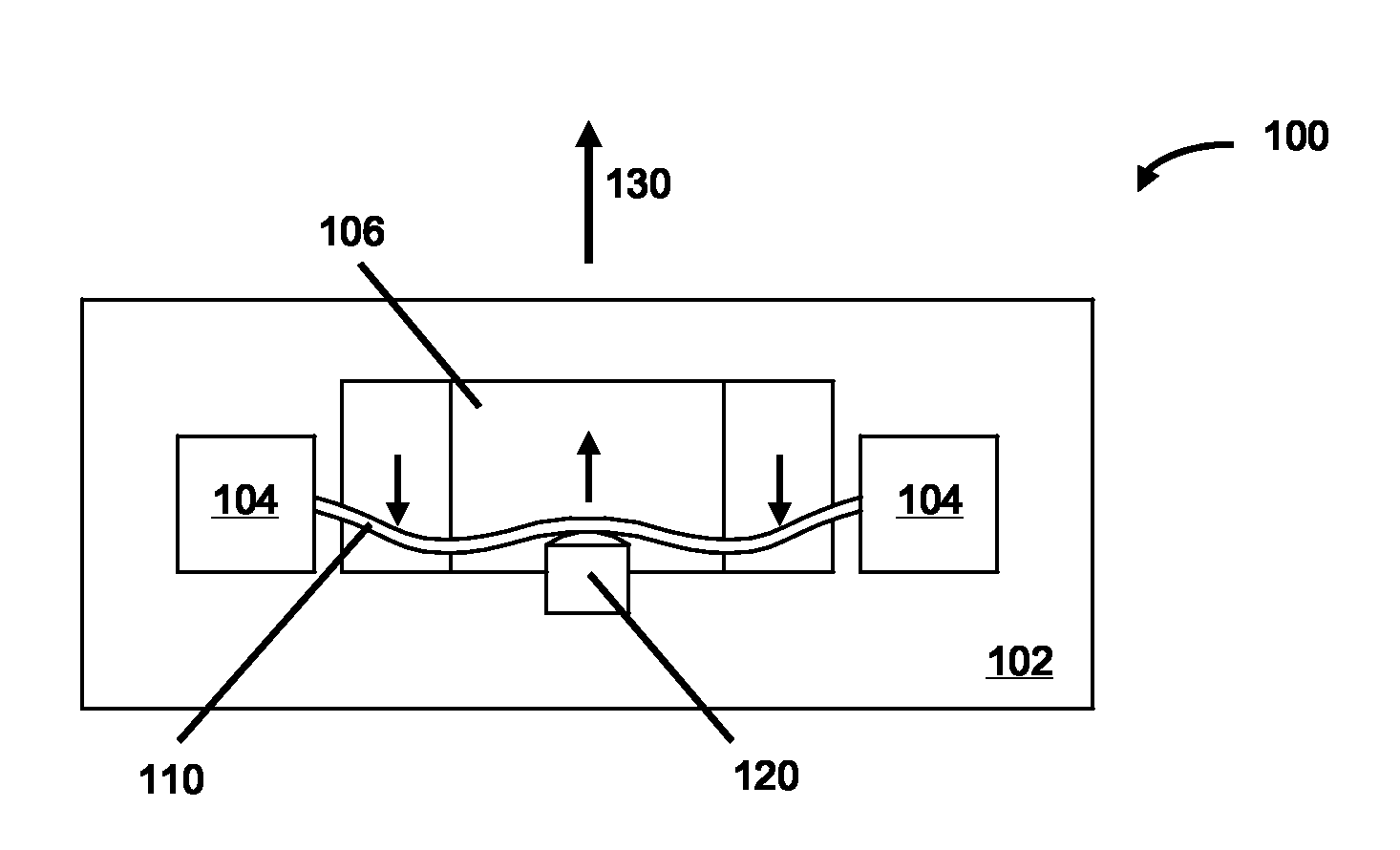
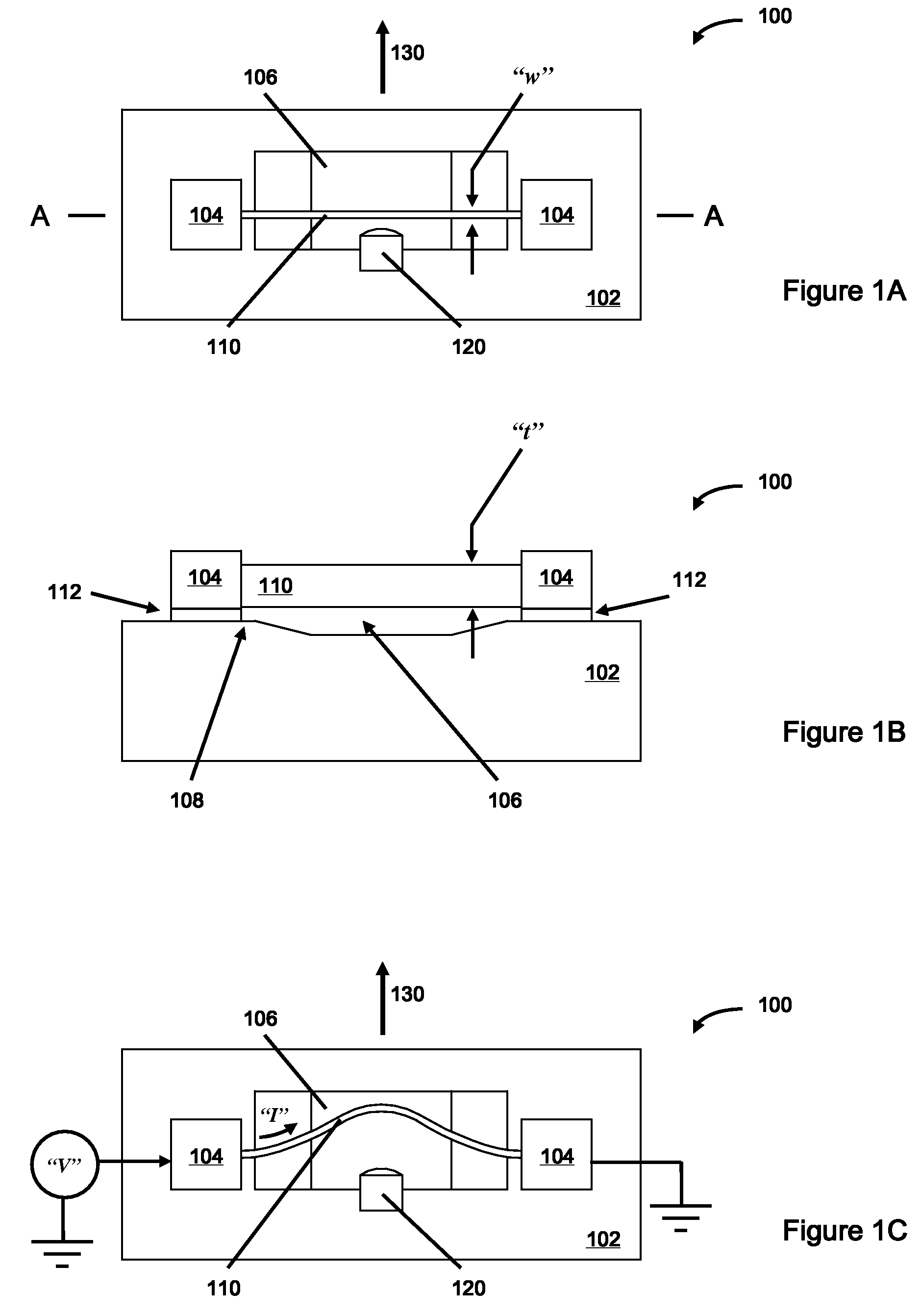
[0029]FIG. 1A is a plan schematic view of an embodiment of a MEM buckling beam thermal actuator according to the present invention. In this exemplary embodiment, MEM buckling beam thermal actuator 100 is presumed to be fabricated in a technology such as the Sandia Ultra-planar Multi-level MEMS Technology (SUMMiT™) technology. MEM buckling beam thermal actuator 100 comprises a silicon substrate 102 upon (and into) the surface of which mechanical structures can be fabricated by the successive dep...


PUM


Abstract

Microelectromechanical (MEM) buckling beam thermal actuators are disclosed wherein the buckling direction of a beam is constrained to a desired direction of actuation, which can be in-plane or out-of-plane with respect to a support substrate. The actuators comprise as-fabricated, linear beams of uniform cross section supported above the substrate by supports which rigidly attach a beam to the substrate. The beams can be heated by methods including the passage of an electrical current through them. The buckling direction of an initially straight beam upon heating and expansion is controlled by incorporating one or more directional constraints attached to the substrate and proximal to the mid-point of the beam. In the event that the beam initially buckles in an undesired direction, deformation of the beam induced by contact with a directional constraint generates an opposing force to re-direct the buckling beam into the desired direction. The displacement and force generated by the movement of the buckling beam can be harnessed to perform useful work, such as closing contacts in an electrical switch.

Description

STATEMENT REGARDING FEDERALLY SPONSORED RESEARCH OR DEVELOPMENT[0001]The United States Government has certain rights in this invention pursuant to Department of Energy Contract No. DE-AC04-94AL85000 with Sandia Corporation.FIELD OF THE INVENTION[0002]The invention generally relates to microelectromechanical (MEM) thermal actuators. The invention additionally relates to MEM thermal actuators comprising beams, mechanically fixed at both ends and heated to induce expansion and eventual buckling of the beam, the buckling motion of the beam producing a force and displacement for the desired actuation. The invention further relates to MEM thermal actuators of the buckling beam type, wherein the buckling direction of the beam is mechanically constrained to the desired direction of actuation, which can be in the plane of, or out of the plane of, a support substrate.BACKGROUND OF THE INVENTION[0003]The invention generally relates to thermal actuators of the buckling beam type, fabricated by ...

Claims


Application Information

Patent Timeline
IPC IPC(8): H01H61/00H01H71/16H01H37/52H01L21/00
CPCB81B3/0024H02N10/00B81B2201/031H01H2061/006
Inventor GARCIA, ERNEST J.FULCHER, CLAY W. G.
Owner NAT TECH & ENG SOLUTIONS OF SANDIA LLC
Why Eureka
Try Eureka