Lens unit and imaging device
a technology which is applied in the field of lens unit and imaging device, can solve the problems of poor molding effect of resin un-filling, difficult shortening of lens unit, and unit having zoom function, and achieves high-performance imaging, small size, and superior optical characteristics.
- Summary
- Abstract
- Description
- Claims
- Application Information
AI Technical Summary
Benefits of technology
Problems solved by technology
Method used
Image
Examples
first embodiment
[First Embodiment]
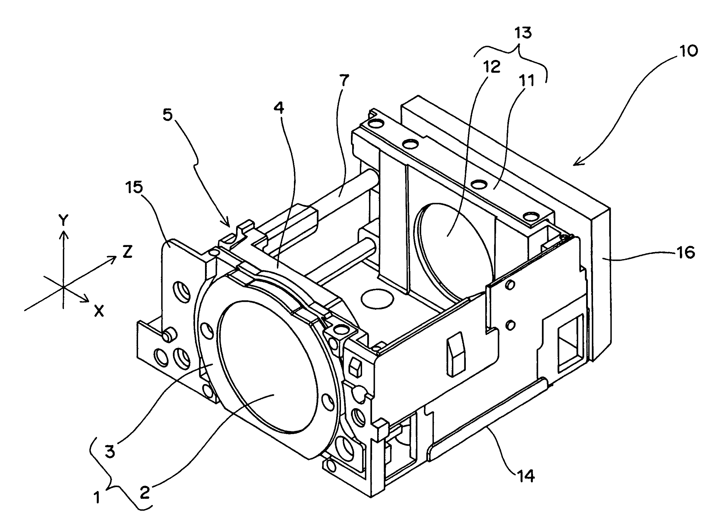
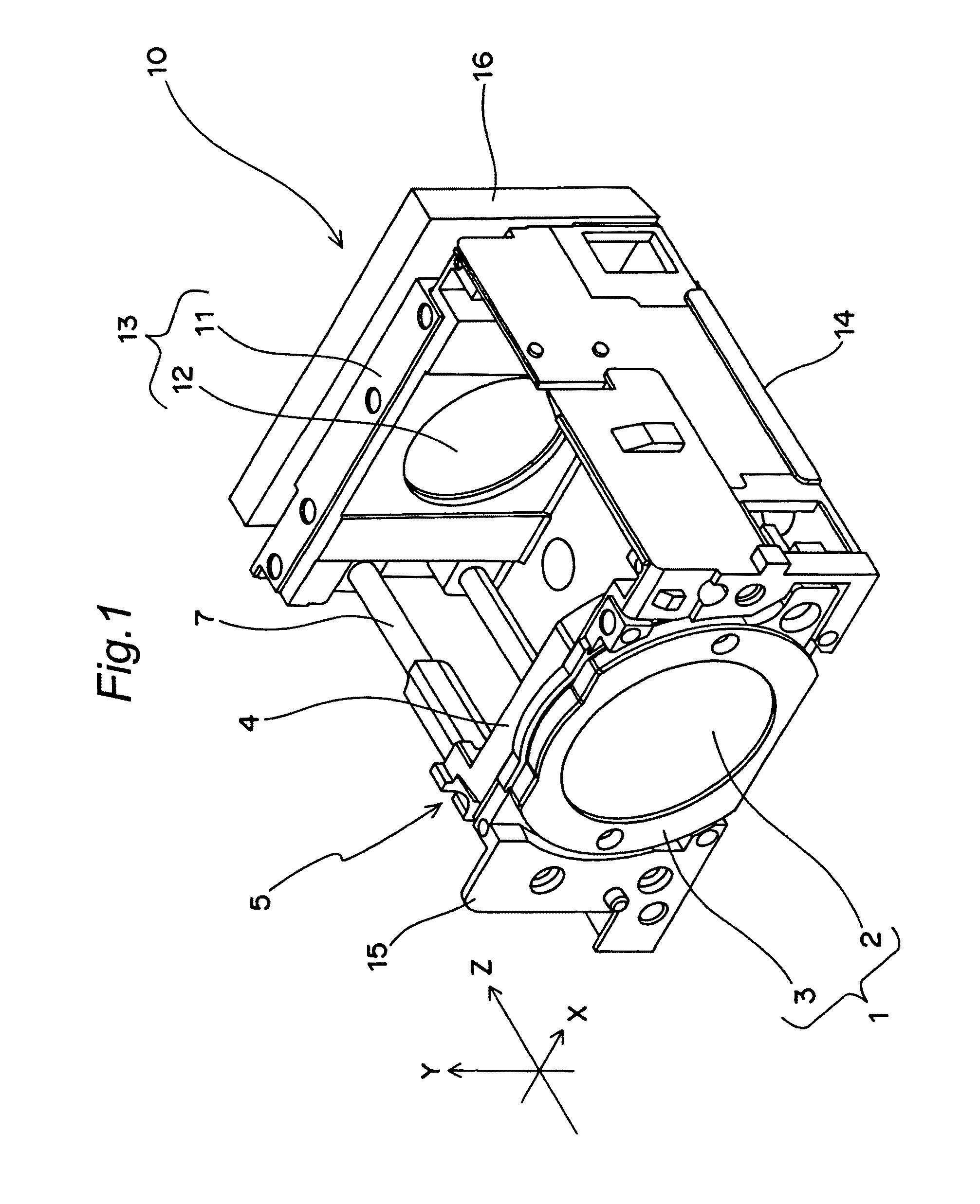
[0041]FIG. 1 is a perspective view of a lens unit according to the first embodiment of the present invention.
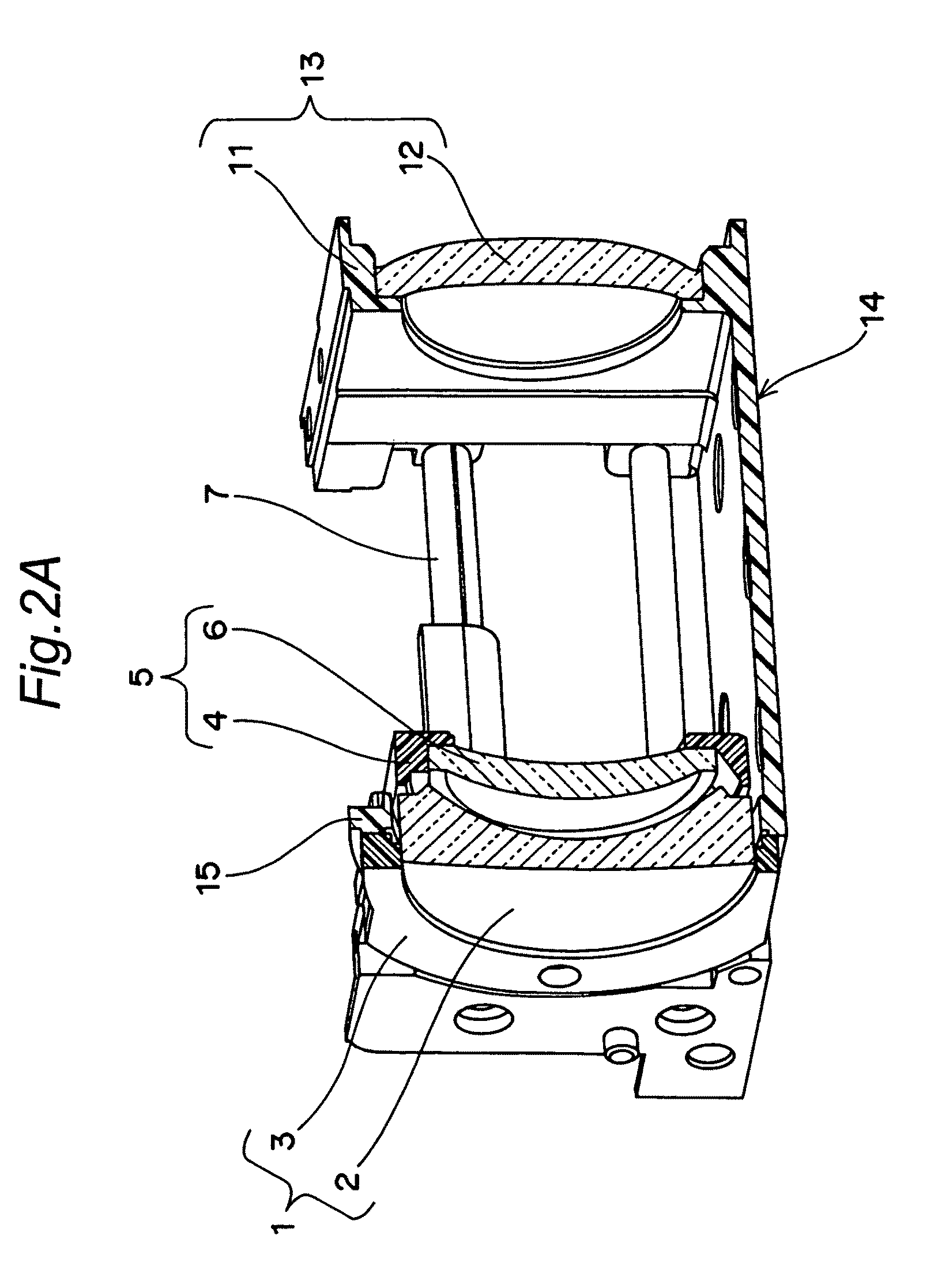
[0042]Here, the direction of a Z-axis is defined as the direction of an optical axis, while the direction of an X-axis and the direction of a Y-axis are defined as the directions of extension of a plane parallel to an imaging surface. The imaging surface has been set on an imaging element 16. FIG. 2A shows a Z-Y section of the lens unit 10 shown in FIG. 1 seen from the direction of the X-axis.
[0043]As shown in FIGS. 1 and 2A, the lens unit 10 has a base 14 shaped like a substantially rectangular plate parallel to the X-Z plane, a first lens group fixing section 15 which is installed at a subject-side end of the base 14 in an upright manner in parallel with the X-Y plane that is substantially normal to a plane of the base 14, and a third lens holder 11 which is installed at an imaging surface-side end of the base 14 in an upright manner in parallel with the X...
second embodiment
[Second Embodiment]
[0067]FIG. 6 is a perspective view of a lens unit according to the second embodiment of the present invention. The lens unit of this embodiment is the same in configuration as the lens unit of the first embodiment, except for a third lent unit 120. Here, the direction of a Z-axis is defined as the direction of an optical axis, while the direction of an X-axis and the direction of a Y-axis are defined as the directions of extension of a plane parallel to an imaging surface. The imaging surface has been set on an imaging element 116. FIG. 7A shows a Z-Y section of the lens unit 110 shown in FIG. 6 seen from the direction of the X-axis.
[0068]As shown in FIGS. 6 and 7A, the lens unit 10 has a base 114 shaped like a substantially rectangular plate parallel to the X-Z plane, a first lens group fixing section 115 which is installed at a subject-side end of the base 114 in an upright manner in parallel with the X-Y plane that is substantially normal to a plane of the base...
PUM
 Abstract
Description
Claims
Application Information
 - R&D
- Intellectual Property
- Life Sciences
- Materials
- Tech Scout
- Unparalleled Data Quality
- Higher Quality Content
- 60% Fewer Hallucinations
Browse by: Latest US Patents, China's latest patents, Technical Efficacy Thesaurus, Application Domain, Technology Topic, Popular Technical Reports.
© 2025 PatSnap. All rights reserved.Legal|Privacy policy|Modern Slavery Act Transparency Statement|Sitemap|About US| Contact US: help@patsnap.com


