Heat exchanger

a technology of heat exchanger and partition member, which is applied in the direction of indirect heat exchanger, refrigeration components, lighting and heating apparatus, etc., can solve the problems of insufficient degree of difficulty in circulating refrigerant, and insufficient uniformity of outflow air temperature, so as to reduce the number of parts, improve the reliability of the joint between the partition member and the cap, and the effect of reducing the number of parts

Inactive Publication Date: 2012-08-07
KEIHIN THERMAL TECH CORP
View PDF13 Cites 10 Cited by
  • Summary
  • Abstract
  • Description
  • Claims
  • Application Information

AI Technical Summary

Benefits of technology

[0006]An object of the present invention is to solve the above problem and to provide a heat exchanger which, when used as an evaporator, can make the outflow air temperature more uniform.
[0021]According to the heat exchangers of pars. 1) to 8), the partition member has a guide portion at an edge portion of the communication opening on the second end side, the guide portion projecting into the second space from a surface of the partition member facing the second space, and guiding the refrigerant to flow toward the first end side. Therefore, even in the case where the amount of refrigerant is large, when the refrigerant flows from the first space into the second space of the refrigerant inlet header section via the communication opening, the refrigerant is guided by the guide portion to smoothly flow toward the first end side; i.e., the end where the refrigerant inlet is formed. Accordingly, the refrigerant is prevented from hitting, due to the flow force, against a portion of the wall of the refrigerant inlet header section to which the heat exchange tubes are connected, the portion corresponding to the communication opening, and changing its flow direction toward the partition member. As a result, the refrigerant becomes more likely to flow into several heat exchange tubes located at the end portion opposite the refrigerant inlet. Therefore, when the heat exchanger is used as an evaporator, the outflow air temperature, which is the temperature of air having passed through the evaporator, is made uniform at the end portion opposite the refrigerant inlet, and the degree of uniformity of the outflow air temperature can be increased.
[0023]According to the heat exchanger of par. 10), the reliability of the joint between the partition member and the caps can be improved. Further, the withstanding pressure of the caps themselves can be increased.
[0024]According to the heat exchanger of par. 11), a refrigerant inlet / outlet header tank having a refrigerant inlet header section and a refrigerant outlet header section can be manufactured relatively easily.
[0025]According to the heat exchanger of par. 12), members identical with the first and second members of the refrigerant inlet / outlet header tank can be used as the first and second members of the refrigerant turn header tank, whereby the number of parts can be reduced.

Problems solved by technology

However, as a result of various studies, the present inventor has found that the evaporator described in the above-described publication has the following problems.
That is, especially in a case where the amount of refrigerant is large, when the refrigerant flows from the first space to the second space of the refrigerant inlet header section via the communication opening, due to the force of the flow, the refrigerant hits against a portion of a wall of the refrigerant inlet header section to which the heat exchange tubes are connected, the portion being generally located just under the communication opening, and changes its flow direction toward the partition member, so that the refrigerant encounters difficulty in flowing into several heat exchange tubes which are located at an end portion opposite the refrigerant inlet.
As a result, outflow air temperature, which is the temperature of air having passed through the evaporator, becomes slightly non-uniform at the end portion opposite the refrigerant inlet, and in some cases the degree of uniformity of the outflow air temperature becomes insufficient.

Method used


Image

  • Heat exchanger
  • Heat exchanger
  • Heat exchanger

Examples


Embodiment Construction

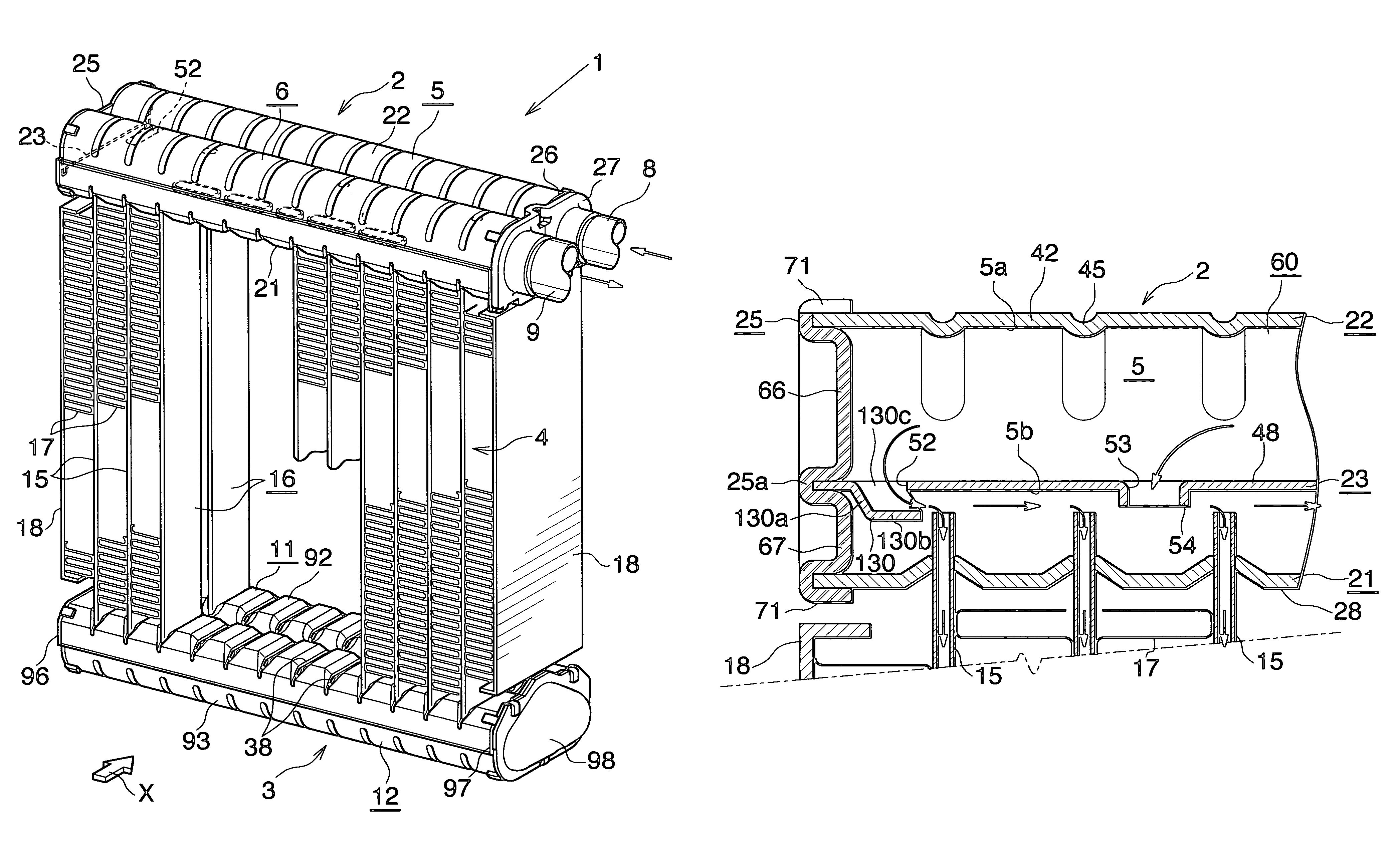
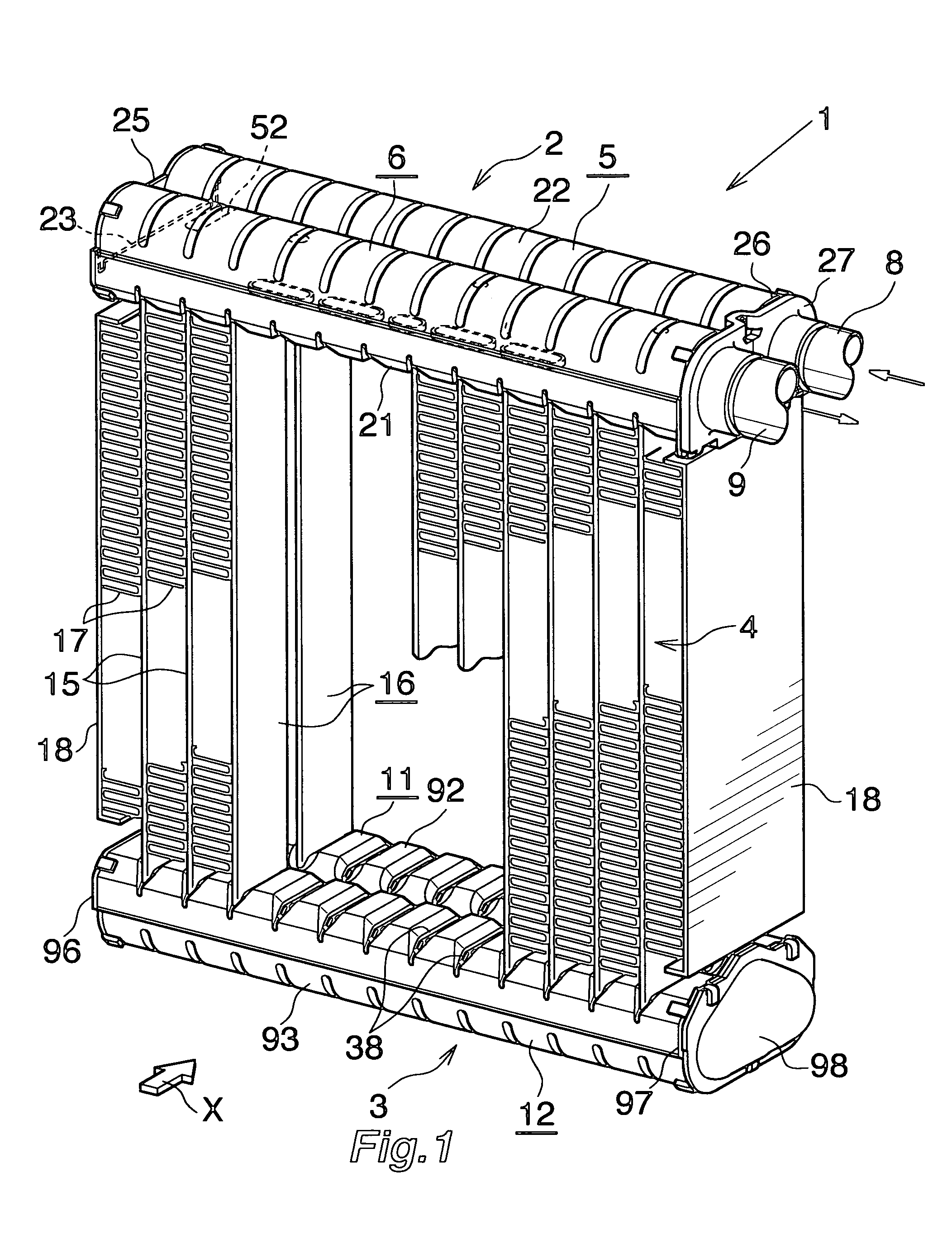
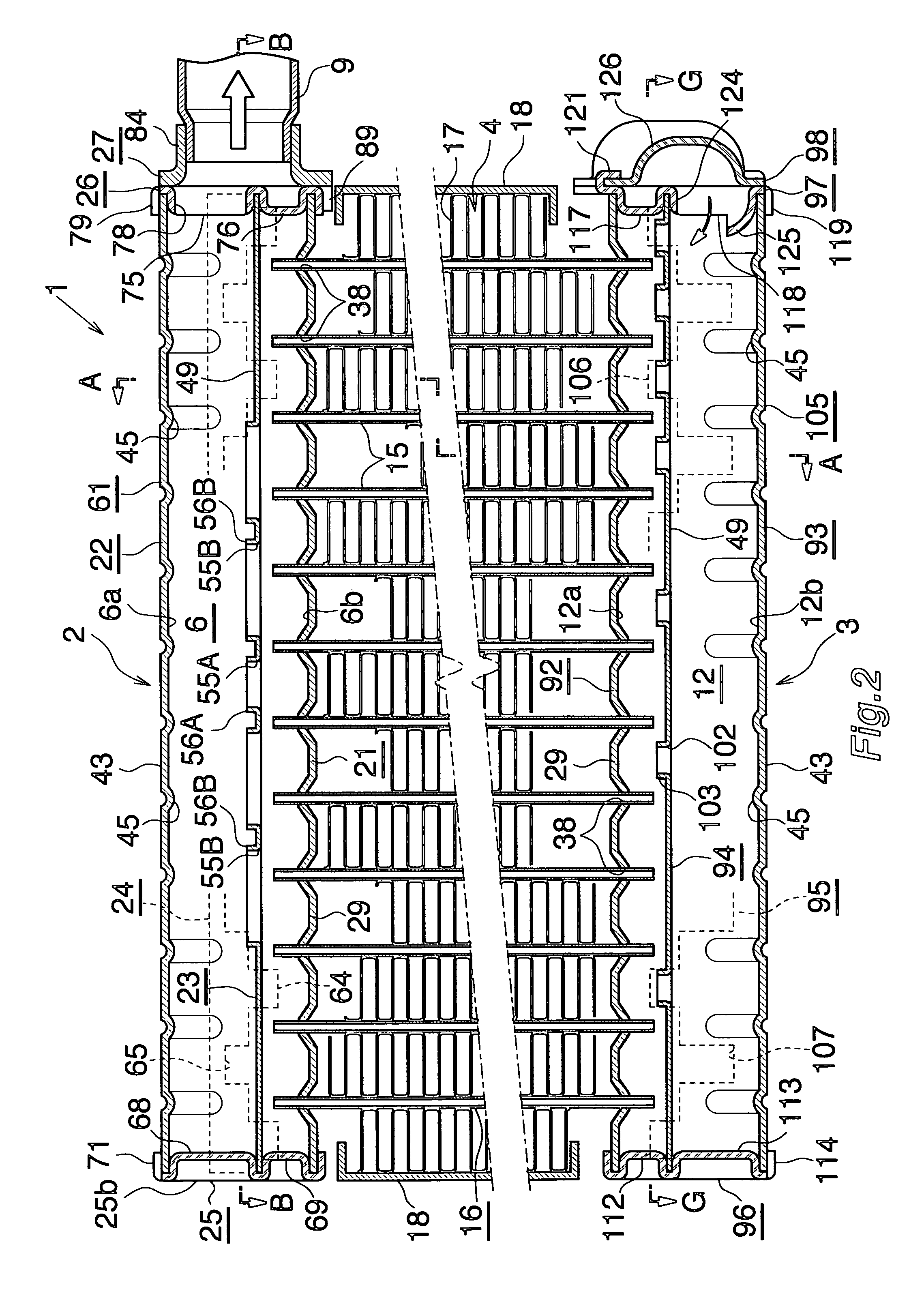
[0043]A preferred embodiment of the present invention will next be described with reference to the drawings. The embodiment is of a heat exchanger according to the present invention that is applied to an evaporator of a car air conditioner using a chlorofluorocarbon-based refrigerant.

[0044]In the following description, the term “aluminum” includes aluminum alloys in addition to pure aluminum. Also, in the following description, the downstream side (a direction represented by arrow X in FIGS. 1, 3, and 4) of an air flow through air-passing clearances between adjacent heat exchange tubes will be referred to as the “front,” and the opposite side as the “rear.” The left-hand and right-hand sides of FIG. 2 will be referred to as “left” and “right,” respectively.

[0045]Further, the same reference numerals are used throughout the drawings to refer to the same portions and members, and their repeated descriptions are omitted.

[0046]FIGS. 1 and 2 show the overall configuration of an evaporator...


PUM


Abstract

A heat exchanger used as an evaporator includes a refrigerant inlet header section having a refrigerant inlet at a right end portion, and a plurality of heat exchange tubes connected to the refrigerant inlet header section. The interior of the refrigerant inlet header section is divided by a partition plate into an upper space into which refrigerant flows via the refrigerant inlet and a lower space into which the heat exchange tubes project. A communication opening is formed in the partition plate on the left side of a heat exchange tube at the left end so as to establish communication between the upper and lower spaces. A guide portion is formed at a left edge portion of the communication opening such that the guide portion projects from a lower surface of the partition member into the lower space so as to guide the refrigerant toward the right end side.

Description

BACKGROUND OF THE INVENTION[0001]The present invention relates to a heat exchanger preferably used as an evaporator of a car air conditioner, which is a refrigeration cycle to be mounted on, for example, an automobile.[0002]Herein and in the appended claims, the upper and lower sides of FIGS. 1 and 2 will be referred to as “upper” and “lower,” respectively.[0003]The applicant of the present application has proposed a heat exchanger used as an evaporator for a car air conditioner which satisfies the needs of reducing size and weight and enhancing performance (see Japanese Patent Application Laid-Open (kokai) No. 2006-132920). The heat exchanger includes a heat exchange core section in which heat exchange tube groups are arranged in two rows in a front-rear direction, each heat exchange tube group consisting of a plurality of heat exchange tubes arranged at intervals; a refrigerant inlet / outlet header tank disposed on an upper-end side of the heat exchange core section; and a refriger...

Claims


Application Information

Patent Timeline
Patent Type & Authority Patents(United States)
IPC IPC(8): F28F9/22
CPCF25B39/028F28D1/05391F28F9/0217F28F9/0246F28D2021/0085F28F1/128F28F9/0224F28F2225/08
Inventor HIGASHIYAMA, NAOHISA
Owner KEIHIN THERMAL TECH CORP
Why Eureka
Try Eureka