PMR write head with narrow gap for minimal internal flux loss

a technology of internal flux loss and write head, which is applied in the field of magnetic shield material, can solve the problem of insignificant flux loss from the main pole to the shield, and achieve the effect of improving field gradient, low internal flux loss, and low cos

Active Publication Date: 2012-08-07
HEADWAY TECH INC
View PDF16 Cites 72 Cited by
  • Summary
  • Abstract
  • Description
  • Claims
  • Application Information

AI Technical Summary

Benefits of technology

[0010]One objective of the present invention is to provide a shield composition and design where the gap between one or more shields and a main pole is narrowed to improve the field gradient with a minimum amount of internal flux loss as required for high area density PMR writers.
[0012]According to the embodiments of the present invention, the first objective is achieved with a shield that is made of a magnetic material with a negative crystalline anisotropy energy constant (-Ku) at room temperature. The shield layer is deposited on a seed layer such as Ru that aligns the c-axis (hard axis) of the hexagonal crystalline structure toward the main pole. The c-axis forms an angle between 0 and 90 degrees with respect to the ABS, and preferably between 20 degrees and 45 degrees with respect to the ABS. Thus, magnetization of the shield can only be induced in a direction toward the main pole with a strong magnetic field. Furthermore, the shield is totally soft in a 2D plane orthogonal to the hard axis which means the magnetization of the shield can be easily induced in any direction orthogonal to the hard axis with a weak magnetic field. As a result, two key requirements of a shield are satisfied by the embodiments described herein and they are (1) providing a magnetic charge at the ABS side of the shield during a write process; and (2) an absence of magnetic charge at the ABS side of the shield in a relaxed state (non-write condition). Furthermore, magnetic charges are minimized on a side of the shield facing the main pole such that flux loss from the main pole to the shield is insignificant.
[0013]According to a first embodiment, the shield structure may comprise one or more of a trailing shield, leading shield, and side shields. In one aspect, the shield structure may be an AWA design that completely surrounds the main pole. In a second embodiment, the novel shield design features a composite shield structure wherein a first section made of an anisotropic (-Ku) magnetic material adjoins the gap layer on one or more sides of the main pole and is closer to the main pole than a second section of the shield structure made of a soft isotropic magnetic material and formed on a side of the first section that faces away from the main pole. The first section is comprised of a magnetic material with a negative crystalline anisotropy constant (-Ku) and has a hard axis aligned toward the main pole. In an embodiment wherein the anisotropic (-Ku) magnetic layer adjoins a write gap, the width of the anisotropic (-Ku) shield layer is preferably greater than that of the adjoining write gap from an ABS view to prevent flux loss from the main pole in a direction toward the shield. When the shield structure is a composite comprising a second (isotropic magnetic) section and the first (anisotropic magnetic) section, there is preferably a non-magnetic metal spacer formed between the first and second sections to prevent interlayer exchange coupling between the -Ku magnetic material and the conventional soft magnetic layer. The non-magnetic spacer may be comprised of Ru with a thickness of 20 to 50 Angstroms.

Problems solved by technology

Furthermore, magnetic charges are minimized on a side of the shield facing the main pole such that flux loss from the main pole to the shield is insignificant.

Method used


Image

  • PMR write head with narrow gap for minimal internal flux loss
  • PMR write head with narrow gap for minimal internal flux loss
  • PMR write head with narrow gap for minimal internal flux loss

Examples


first embodiment

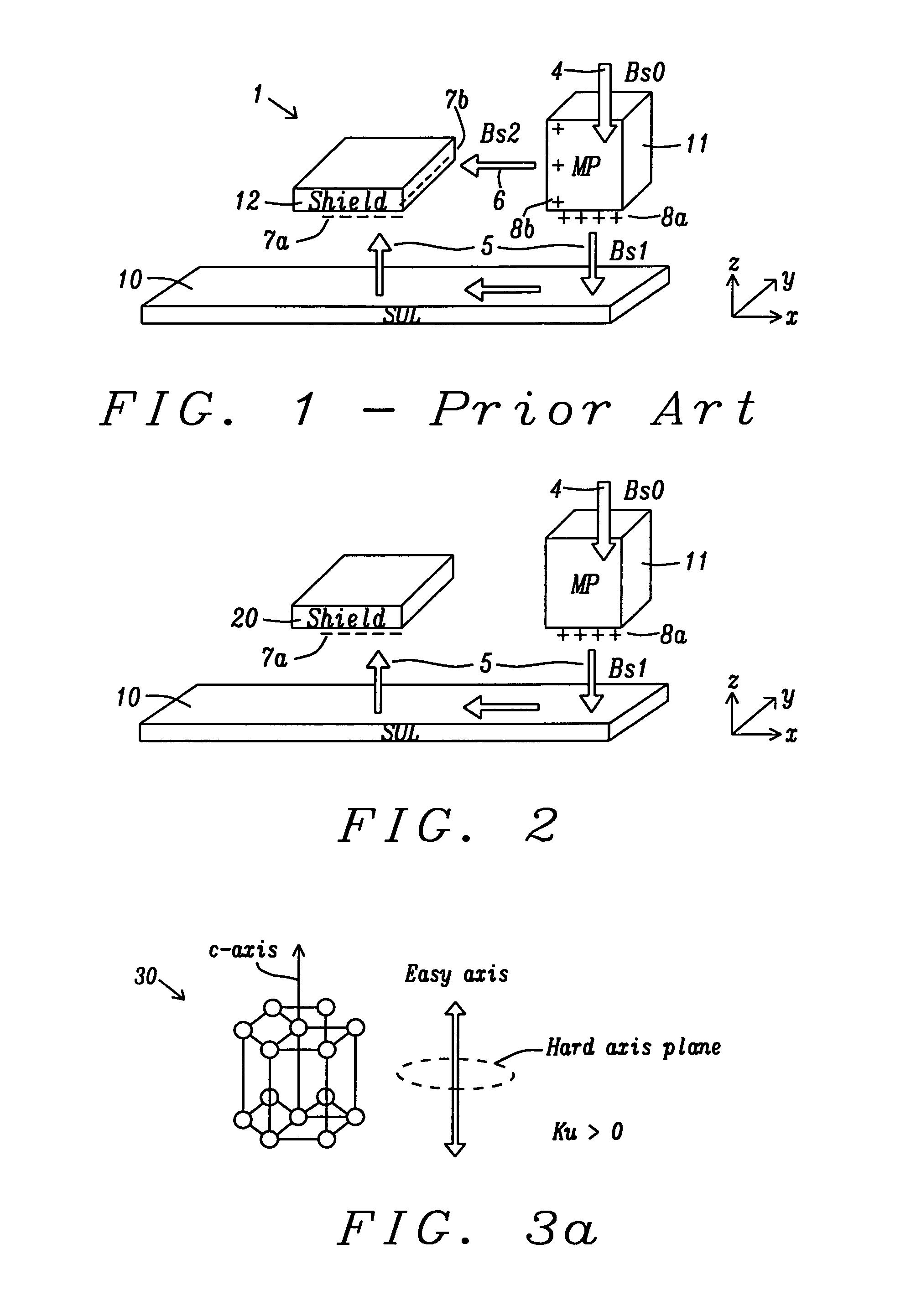
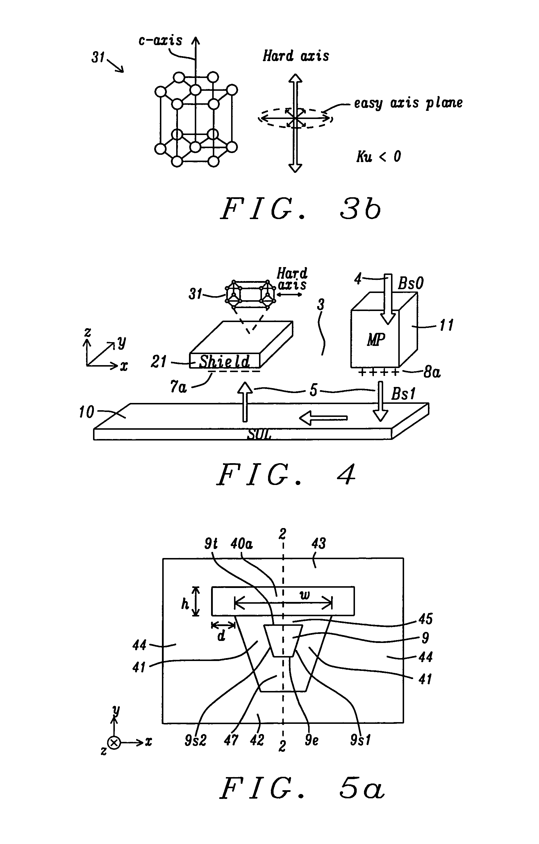
[0038]Referring to FIG. 4, the present invention is shown wherein a shield 21 made of an anisotropic (-Ku) magnetic material with a plurality of crystals 31 and a hard axis in the x-axis direction is advantageously used to prevent flux leakage from a main pole 11 formed in a x-axis direction from the shield 21 and separated therefrom by gap 3. By depositing the shield layer on an appropriate seed layer (not shown), the c-axis of each hexagon crystal 31 is pointing toward the main pole. Magnetic charges 7a are still generated at the ABS of the shield 21 during a write process to facilitate the desired flow 5 of flux from the main pole 11 into the magnetic medium 10, and then into the shield 21. The magnetization direction of the shield 21 may be induced orthogonal to the hard axis by a weak magnetic field which has a magnitude less than about 20 Oe.

second embodiment

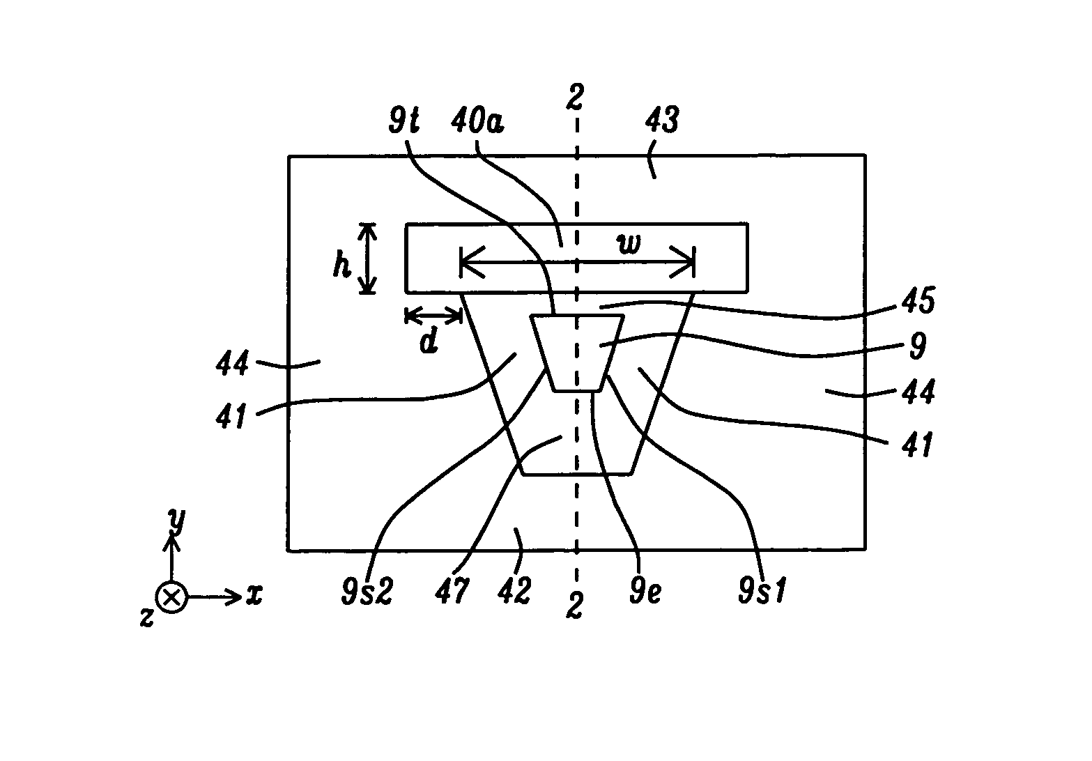
[0039]Referring to FIG. 5a, the present invention is shown from an ABS view and includes a main pole 9 having a trapezoidal shape with a leading edge 9e that has a smaller width in a cross-track (x-axis) direction than the trailing edge 9t. Sloped sides 9s1, 9s2 of the main pole are adjoined by a side gap 41 made of a dielectric material. Main pole 9 may include a seed layer (not shown) along sides 9s1, 9s2 and along leading edge 9e that facilitates a deposition method wherein main pole material is plated in an opening bounded by side gaps 41 and lead gap 47. In the exemplary embodiment, the side gap has a uniform width in the x-axis direction and conforms to the shape of the sides 9s1, 9s2. There is also a write gap 45 having a width w that adjoins a top surface of each side gap 41 and interfaces with the trailing edge 9t of the write pole. The write gap may be comprised of the same dielectric material as in the side gap. A leading gap 47 interfaces with the leading edge 9e and adj...

fifth embodiment

[0049]The fifth embodiment also anticipates that a non-magnetic metal layer 65 made of Ru, for example, may be formed between each first shield section and an adjacent second shield section to prevent interlayer coupling between first and second shield sections. Thus, the non-magnetic metal layer 65 forms a contiguous layer and separates first trailing shield section 40a from second trailing shield section 43, first side shield section 40b (and 40d) from a second side shield section 44, and first leading shield section 40c from second leading shield section 42. A method of forming the shield structure in FIG. 8 is not provided here. However, a combination of fabrication processes described with regard to FIGS. 9-16 may be employed to make the AWA shield structure where there is a contiguous anisotropic (-Ku) magnetic shield layer surrounding the main pole as appreciated by those skilled in the art.

[0050]Referring to FIG. 9, an intermediate structure formed during the fabrication of ...


PUM

PropertyMeasurementUnit
thicknessaaaaaaaaaa
thicknessaaaaaaaaaa
angleaaaaaaaaaa

Abstract

A PMR writer is disclosed wherein one or more of a trailing shield, leading shield, and side shields are composites with a first section made of an anisotropic (-Ku) magnetic layer adjoining a gap layer and a second section comprised of an isotropic soft magnetic layer formed on a side of the first section that faces away from the main pole. There may be a non-magnetic Ru layer between each first and second section to prevent interlayer coupling. Each first section has a hard axis in a direction toward the main pole and is comprised of hcp-CoIr, dhcp-CoFe, a′-Fe—C, or NiAs-type Mn50Sb50 with a thickness from 50 to 500 nm. As a result, flux leakage from the main pole to a shield structure is reduced and area density is increased. A method for fabricating a composite shield structure is also provided.

Description

FIELD OF THE INVENTION[0001]The invention relates to a magnetic shield material having a hard axis aligned towards the main pole and a magnetic softness in a 2D plane orthogonal to the hard axis in order to minimize flux loss between the main pole and adjacent shields, and to avoid a magnetic charge at the ABS of magnetic shields in a non-write condition.BACKGROUND OF THE INVENTION[0002]In today's perpendicular magnetic recording (PMR) technology, an all wrapped around (AWA) shield writer is widely used by the major hard disk drive (HDD) manufacturers. The function of a trailing shield in an AWA structure is to improve the magnetic field gradient along a down track direction which is a key requirement for high bits per inch (BPI). Meanwhile, side shields and a leading shield serve to define a narrower writer bubble which is important for realizing higher tracks per inch (TPI). In order to achieve higher area density (i.e. higher BPI and TPI) in advanced writer designs, the gap betwe...

Claims


Application Information

Patent Timeline
Patent Type & Authority Patents(United States)
IPC IPC(8): G11B5/127
CPCG11B5/1278G11B5/3116G11B5/23G11B5/315G11B5/3163
Inventor TANG, YUHUIGUAN, LIJIEMIN, TAISONG, SUPING
Owner HEADWAY TECH INC
Why Eureka
Try Eureka