
Adjustable partial annuloplasty ring and mechanism therefor
a partial annuloplasty and annuloplasty ring technology, applied in the field of valve repair, can solve the problems of reducing cardiac output, increasing total stroke volume, and ultimate weakening of the left ventricle, and achieve the effect of facilitating the contracting of the annuloplasty structur
- Summary
- Abstract
- Description
- Claims
- Application Information
AI Technical Summary
Benefits of technology
Problems solved by technology
Method used
Image

Examples
Embodiment Construction
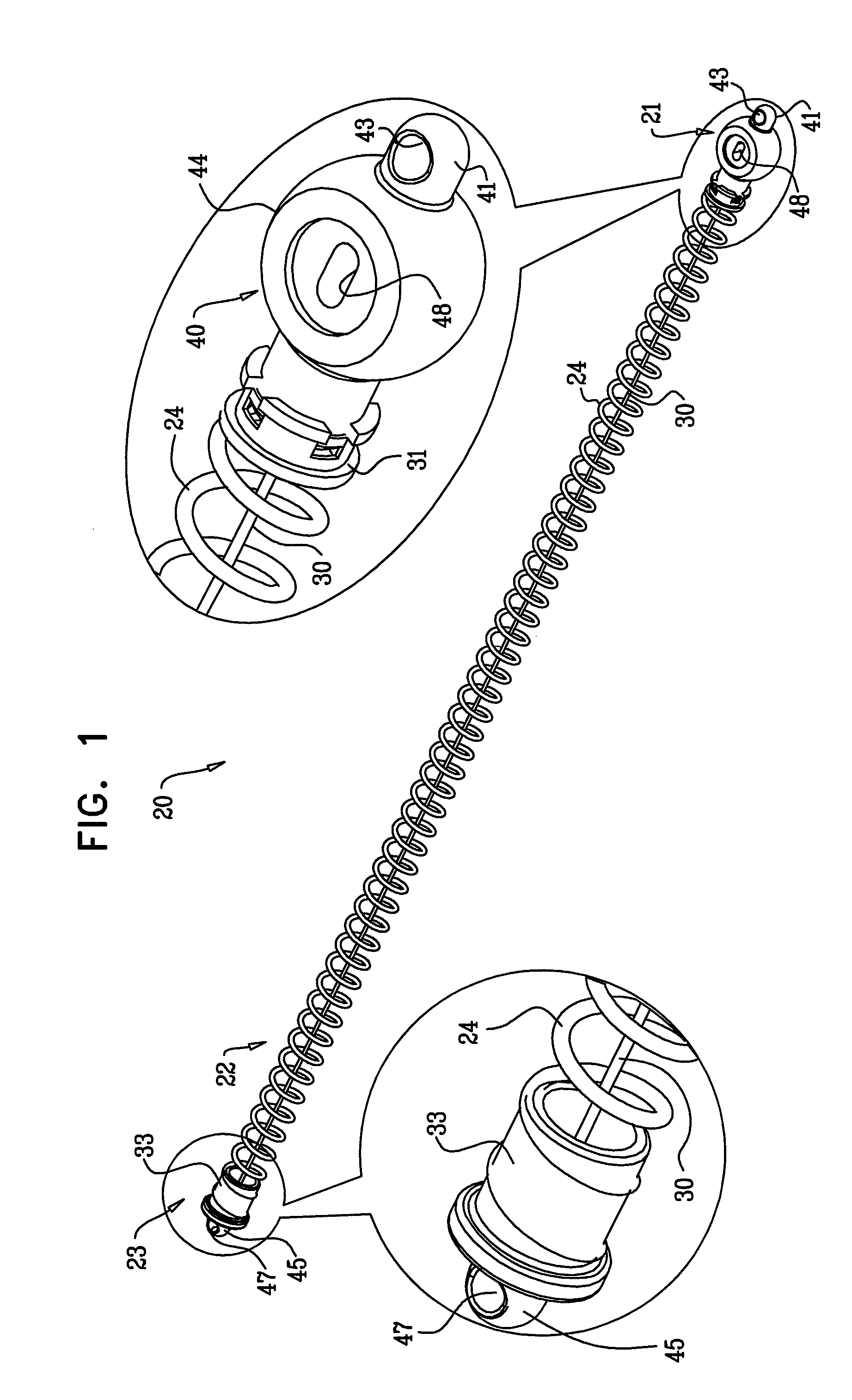
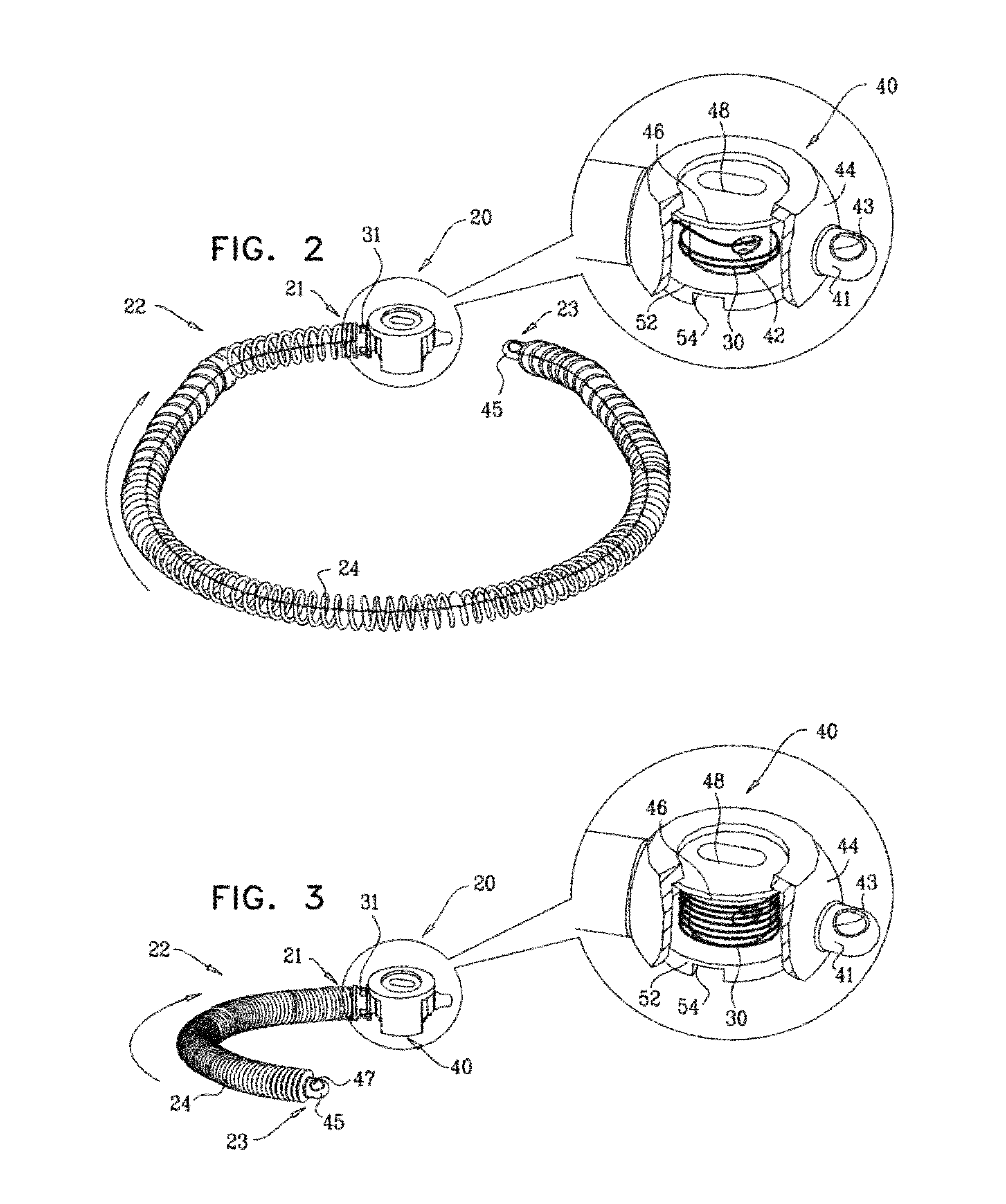
[0185]Reference is now made to FIGS. 1-3, which are schematic illustrations of a system 20 for repairing a dilated annulus of a subject comprising an implant structure, e.g., an annuloplasty structure 22, comprising a body portion 24, a flexible member 30, and a contracting mechanism 40, in accordance with an embodiment of the present invention. FIG. 1 shows structure 22 in a resting state thereof in which structure 22 defines a linear, elongate structure having a longitudinal axis thereof. At least a portion, e.g., the entirety, of body portion 24 comprises a compressible material, e.g., a coiled element, as shown by way of illustration and not limitation. For example, body portion 24 may comprise stent-like struts, or a braided mesh. Typically, body portion 24 defines a lumen along the longitudinal axis of structure 22 which houses flexible member 30. Flexible member 30 comprises a wire, a ribbon, a rope, or a band, comprising a flexible metal. Flexible member 30 is coupled at a f...
PUM
 Abstract
Description
Claims
Application Information