Projector

a projector and projection device technology, applied in the field of projectors, can solve problems such as burdening users, and achieve the effects of reducing the dispersion of identification accuracy, facilitating calculation of position information, and convenient execution

Inactive Publication Date: 2012-08-14
FUNAI ELECTRIC CO LTD
View PDF10 Cites 13 Cited by
  • Summary
  • Abstract
  • Description
  • Claims
  • Application Information

AI Technical Summary

Benefits of technology

[0014]According to the present invention, because the invention is configured in order that the determination section specifies the reflection position of the reflected light received by the light receiving sensor and determines the amplification quantity of the intensity of the reflected light reflected at the specified reflection position to be received by the light receiving sensor, it becomes possible to adjust the amplification quantity in consideration of the influences of the attenuation rate of the light intensity of the reflected light and the like according to the reflection position, and consequently it is possible to suppress the dispersion of the accuracy of the identification of an external obstacle according to the reflection position. Moreover, because the calculation section can easily calculate the position information of the external obstacle on the basis of the timing of identifying the external obstacle with the identification section, the horizontal synchronizing signal, and the pixel clock signal, no particular configurations for detecting the position of the external obstacle are needed. Moreover, because the calculation of the position information is not performed on the basis of the light quantity of the reflected light received by the light receiving sensor, no complicated operation are also needed.
[0015]Consequently, the present invention can be said to be a projector that can easily execute the position detection of the external obstacle and that can perform the identification of the external obstacle with high identification accuracy.

Problems solved by technology

However, there is frequently the case where it becomes a burden for the user to point a desired point with a point device, such as the pointing rod or the laser pointer, or the input device, such as the touch panel or the mouse, in some environments of the installation of the projector.

Method used


Image

  • Projector
  • Projector
  • Projector

Examples


Embodiment Construction

[0029]In the following, an embodiment of the present invention will be described with reference to the attached drawings. The scope of the invention is not limited to the illustrated examples.

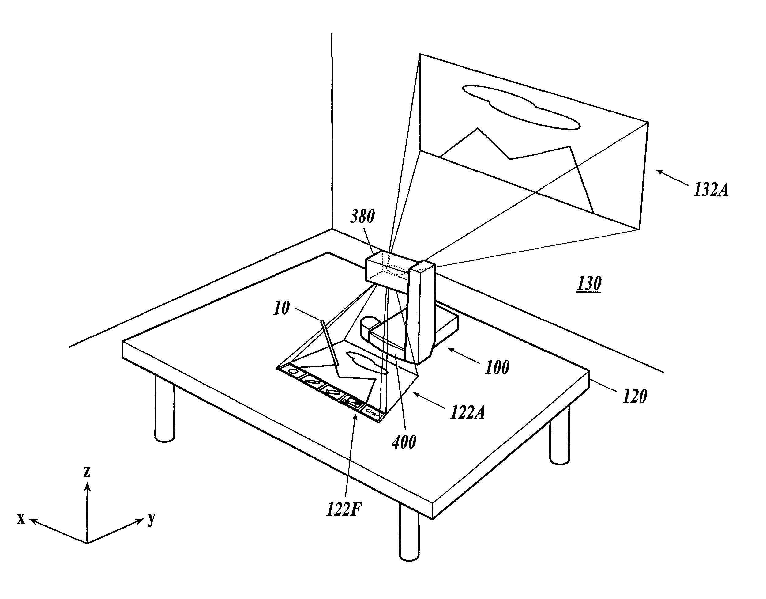
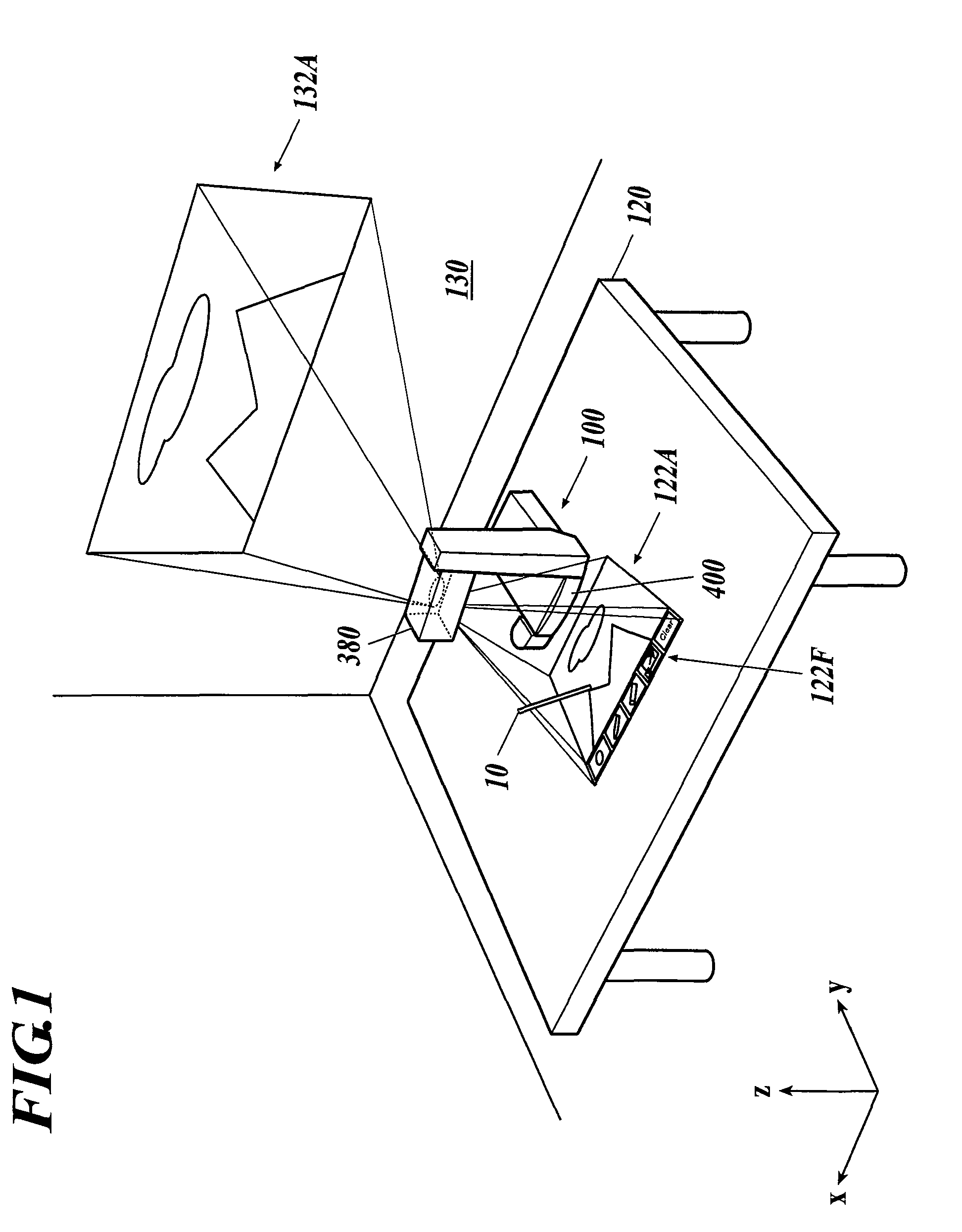
[0030]Moreover, in the following description, the right-left direction of a projector 100 in FIG. 1 is set as an X direction; the front-back direction thereof is set as a Y direction; and the height direction thereof is set as a Z direction.

[0031]The projector 100 is installed on, for example, a table 120 as shown in FIG. 1. The projector 100 is a laser projector projecting a laser light (second laser light) emitted toward a screen 130 to form a displaying image 132A, to be used for presentation and the like by a projection section 380.

[0032]Moreover, the projector 100 projects an image 122A similar to the image 132A (the size of the image 122A is generally smaller than that of the image 132A) onto the top surface of the table 120 with a laser light (first laser light) split by the projection s...


PUM


Abstract

A projector includes a determination section, an amplification section, an identification section and a calculation section. The determination section specifies a reflection position of a reflected light received by a light receiving sensor based on a horizontal synchronizing signal and a pixel clock signal of an image signal, and determines an amplification quantity of the intensity of a reflected light reflected at the specified reflection position to be received by the light receiving sensor. The amplification section amplifies the intensity of the reflected light received by the light receiving sensor by the determined amplification quantity. The identification section identifies an external obstacle when the intensity of the amplified reflected light exceeds a predetermined threshold value. The calculation section calculates the position information of the external obstacle based on the timing of identifying the external obstacle, the horizontal synchronizing signal, and the pixel clock signal of the image signal.

Description

BACKGROUND OF THE INVENTION[0001]1. Field of the Invention[0002]The present invention relates to a projector.[0003]2. Description of Related Art[0004]A laser projector is known hitherto as a projector projecting an image input from the outside with a laser light. Because this projector is used by projecting an image at a distant position generally, it is necessary for a user to use a pointing rod reaching the position of the image from the position of the user or a laser pointer performing laser irradiation to the image in order that the user points a desired point in the projected image. Moreover, if other information equipment connected to the projector inputs an image, then the user points a desired point with an input device, such as a touch panel or a mouse, equipped in the other information equipment.[0005]However, there is frequently the case where it becomes a burden for the user to point a desired point with a point device, such as the pointing rod or the laser pointer, or ...

Claims


Application Information

Patent Timeline
Patent Type & Authority Patents(United States)
IPC IPC(8): G01B11/14
CPCG03B21/132H04N9/3194H04N9/3147H04N9/3129
Inventor NISHIGAKI, HIROSHIHIRANO, ATSUYACHIKAOKA, ATSUHIKONISHIOKA, KEN
Owner FUNAI ELECTRIC CO LTD
Why Eureka
Try Eureka