Curved element, wing, control surface and stabilizer for aircraft

a technology of control surface and stabilizer, which is applied in the direction of aircraft accessories, aircraft floors, wings, etc., can solve the problems of discontinuities between separate parts and slow assembly of such curved elements, and achieve the effect of avoiding discontinuities and facilitating and fast manufacturing of curved elements

Inactive Publication Date: 2012-08-21
PATRIA AEROSTRUCTURES
View PDF16 Cites 24 Cited by
  • Summary
  • Abstract
  • Description
  • Claims
  • Application Information

AI Technical Summary

Benefits of technology

[0010]An advantage of the invention is that the manufacture of the curved element is easier and faster, the reinforcements being integrated into the skin plates of the curved element. Furthermore, as regards strength, reinforcements integrated into a structure are better than a plurality of separate reinforcement pieces to be fastened to the skin plates. This enables the avoidance of discontinuities between the reinforcements integrated into the structure and the skin plates.
[0011]The idea of an embodiment of the invention is that the curved element is provided with reinforcements directed in at least two directions transverse relative to each other, the directed reinforcements forming a latticed reinforcement structure in the curved element, which is advantageous as regards strength.
[0015]The idea of an embodiment of the invention is that a thickening provided in the skin plate or the skin plate profile constitutes the profile reinforcement, the thickening having a larger material thickness compared with the sections between the profile reinforcements. The arrangement of such a thickening into the structure is quite simple.

Problems solved by technology

However, the assembly of such curved elements from a plurality of separate components is slow.
Furthermore, discontinuities exist between the separate parts, which is undesirable from the point of view of the strength theory.

Method used


Image

  • Curved element, wing, control surface and stabilizer for aircraft
  • Curved element, wing, control surface and stabilizer for aircraft
  • Curved element, wing, control surface and stabilizer for aircraft

Examples


Embodiment Construction

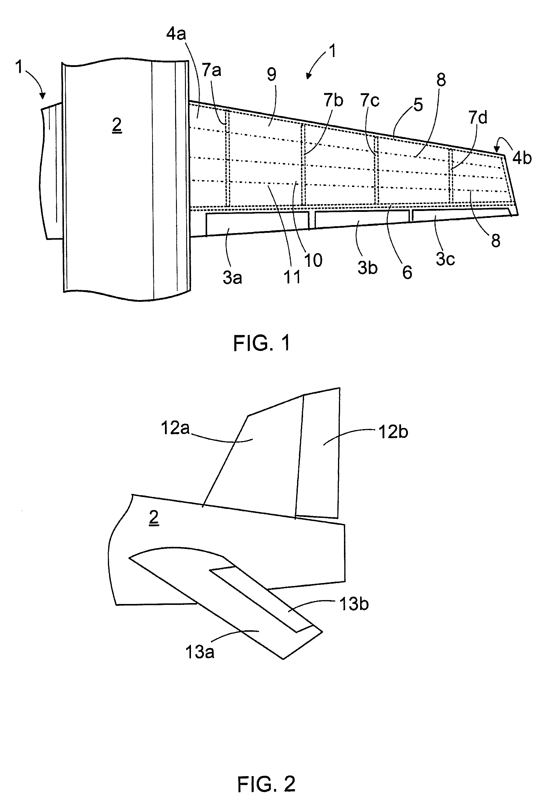
[0043]FIG. 1 shows a wing 1 that is fastened to a frame 2 of an aircraft. The trailing edge of the wing 1 may comprise movable control surfaces 3a to 3c. The wing 1 may comprise an upper skin plate 4a and a lower skin plate 4b, between which is arranged a support structure for the wing that may comprise a front spar 5 and a rear spar 6, and a plurality of wing ribs 7 arranged between the spars. Thus, the front and rear bars 5, 6 are reinforcements substantially in the longitudinal direction of the wing, whereas the wing ribs 7 are reinforcements in the transverse direction of the wing. In addition, the support structure may include a plurality of stringers 8, which may be fastened to the inner surface of the skin plates 4a, 4b and to the wing ribs 7. The wing rib 7 may be a curved element of the invention.

[0044]FIG. 2 shows the tail of an airplane, comprising fixed stabilizers 12a, 13a, and movable control surfaces 12b, 13b. The support structures of these stabilizers and control su...


PUM


Abstract

A curved element, a wing, a control surface and a stabilizer for an aircraft. The curved element (7) is of a composite material and comprises surfaces (14, 21) provided with a plurality of profile reinforcements (20, 25). The profile reinforcements constitute an integrated part of the structure of the surfaces and have a directed strength effect. The profile reinforcements may be arranged in a manner constituting a latticed support structure.

Description

BACKGROUND OF THE INVENTION[0001]The invention relates to a curved element for use in the support structures of the wings and control surfaces of an aircraft. The invention further relates to a wing, a control surface and a stabilizer for an aircraft. The object of the invention is disclosed more closely in the preambles of the independent claims.[0002]The wing of aircrafts, such as airplanes and the like, comprises skin plates, between which the actual support structure of the wing is arranged and typically comprises a front spar and a rear spar in the longitudinal direction of the wing and wing ribs connecting them in the transverse direction of the wing. Usually a plurality of stringers is further provided between the wing ribs and the skin plates. The structure of the stabilizers and the control surfaces, such as spoilers, landing flanges, rudders etc., for example, is typically similar to that of the wing and comprises curved elements corresponding to the wing ribs.[0003]Instea...

Claims


Application Information

Patent Timeline
Patent Type & Authority Patents(United States)
IPC IPC(8): B64C1/00
CPCB64C3/187B64C1/00B64C3/18B64C5/00
Inventor MAKELA, JUHAHALME, JUHAHALME, LAURIHOFFREN, MIKKO
Owner PATRIA AEROSTRUCTURES
Why Eureka
Try Eureka