Fluid shear actuated hoist brake

a technology of hydraulic shear and hoist brake, which is applied in the direction of hoisting equipment, mechanical equipment, shock absorbers, etc., can solve the problems of complex arrangement involving a substantial number of components, system complexity, and inability to simply free-fall the load, and achieve the effect of free rotation of the sha

Active Publication Date: 2012-08-21
HESS DANIEL L
View PDF23 Cites 4 Cited by
  • Summary
  • Abstract
  • Description
  • Claims
  • Application Information

AI Technical Summary

Benefits of technology

[0006]The present invention provides an improved hoist brake mechanism which uses directional fluid shear to cause application of a main brake when a drum shaft rotates in a lowering direction to cause controlled lowering of a load and which releases the main brake when the shaft rotates in an opposite lift direction to enable substantially free rotation of the shaft during lifting.
[0011]In an embodiment of the hoist brake mechanism, the main brake is formed by a main disc stack including a plurality of rotary main discs interleaved among a plurality of fixed main discs. The rotary main discs are slidable relative to the inner hub, such as by spline teeth on center openings of the rotary main discs and axial splines on the inner hub. The fixed main discs are slidably engaged with the outer hub, as by external spline teeth on the outer edges of the fixed main discs and axial splines on an inner surface of the outer hub. Compression of the main disc stack causes a drag or braking effect to retard and / or stop rotation of the shaft. Although it is foreseen that the main disc stack could be dry, relying only on friction among the discs for braking, an embodiment of the main disc stack is immersed in a fluid similar to that of the actuator disc stack. By this means an increasing amount of braking occurs as a result of fluid shear generated by relative rotation of the rotary and fixed main discs as the main disc stack is compressed, and additional braking occurs by surface friction when the rotary and fixed discs touch because of strong axial compression.
[0014]When the actuator hub is rotated in the lowering direction, the closed end of the actuator hub urges the actuator disc stack against the actuator end of the actuator sleeve, thereby urging the main end of the actuator sleeve against the main disc stack. In the process, the main disc stack is axially compressed between the main end of the actuator sleeve and the closed end of the outer hub, while the actuator disc stack is axially compressed between the closed end of the actuator hub and the actuator end of the actuator sleeve. Thus, the actuator disc stack forms an assist brake section which contributes to the braking effect, along with the main disc stack.
[0015]In addition to automatic partial application of the main brake during lowering of a load, the hoist brake mechanism is provided with a manual control to enable an increased braking effect to stop lowering or lifting of a load or to decrease braking of the hoist shaft. In an embodiment of the hoist brake mechanism, a brake operating lever is secured to the actuator hub on the closed end wall to enable manual rotation of the actuator hub in the lowering direction to increase the braking effect by axial engagement of the actuator hub with the main brake or rotation of the actuator hub in the lift direction do decrease the braking effect. Manual operation of the brake operating lever may be accomplished either directly or indirectly by an arrangement of mechanical links or linkages. It is also foreseen that operation of the brake operating lever may be accomplished remotely using electrical, hydraulic, pneumatic, or similar means to selectively apply an angular force on the actuator hub.
[0016]Over time, wear on the discs of the main brake disc stack and / or the actuator disc stack can diminish the thickness of the discs. Because of this, the actuator hub would have to travel axially a longer distance from an initial starting position to achieve the same braking effect. To overcome this, an embodiment of the hoist brake mechanism provides a means of adjustment of the angular relationship between the brake operating lever and the actuator hub and, thus, provides a means of biasing or calibrating the initial position of the actuator hub for a given angular position of the brake operating lever. In one embodiment of the lever, a worm and worm wheel or spur gear arrangement is provided with the worm mounted on the lever and a spur gear secured to the closed end wall of the actuator hub. The lever adjustment arrangement can also be used to set the initial position of the actuator hub if the brake discs are replaced with thicker new discs.

Problems solved by technology

During a long lowering operation, the load is not allowed to simply free-fall, especially with a particularly heavy load, since the load would likely accelerate out of control.
Such systems tend to be complex.
However, this is a complex arrangement involving a substantial number of components which do not directly retard rotation of the shaft.
The limit is based on the strength of the components and on the amount of braking friction that can be generated.
Over time, braking friction creates wear on the brake elements, such as on stacks of rotary and fixed brake discs.
If a hoist employing such a brake is typically used for lifting loads which are significantly below the upper load limit, wear often occurs on more brake elements than is necessary.
However, with most hoist brake designs, there is no way to vary the number of brake elements to an optimum number for the size of the load normally lifted by the hoist.

Method used


Image

  • Fluid shear actuated hoist brake
  • Fluid shear actuated hoist brake
  • Fluid shear actuated hoist brake

Examples


Embodiment Construction

[0028]As required, detailed embodiments of the present invention are disclosed herein; however, it is to be understood that the disclosed embodiments are merely exemplary of the invention, which may be embodied in various forms. Therefore, specific structural and functional details disclosed herein are not to be interpreted as limiting, but merely as a basis for the claims and as a representative basis for teaching one skilled in the art to variously employ the present invention in virtually any appropriately detailed structure.

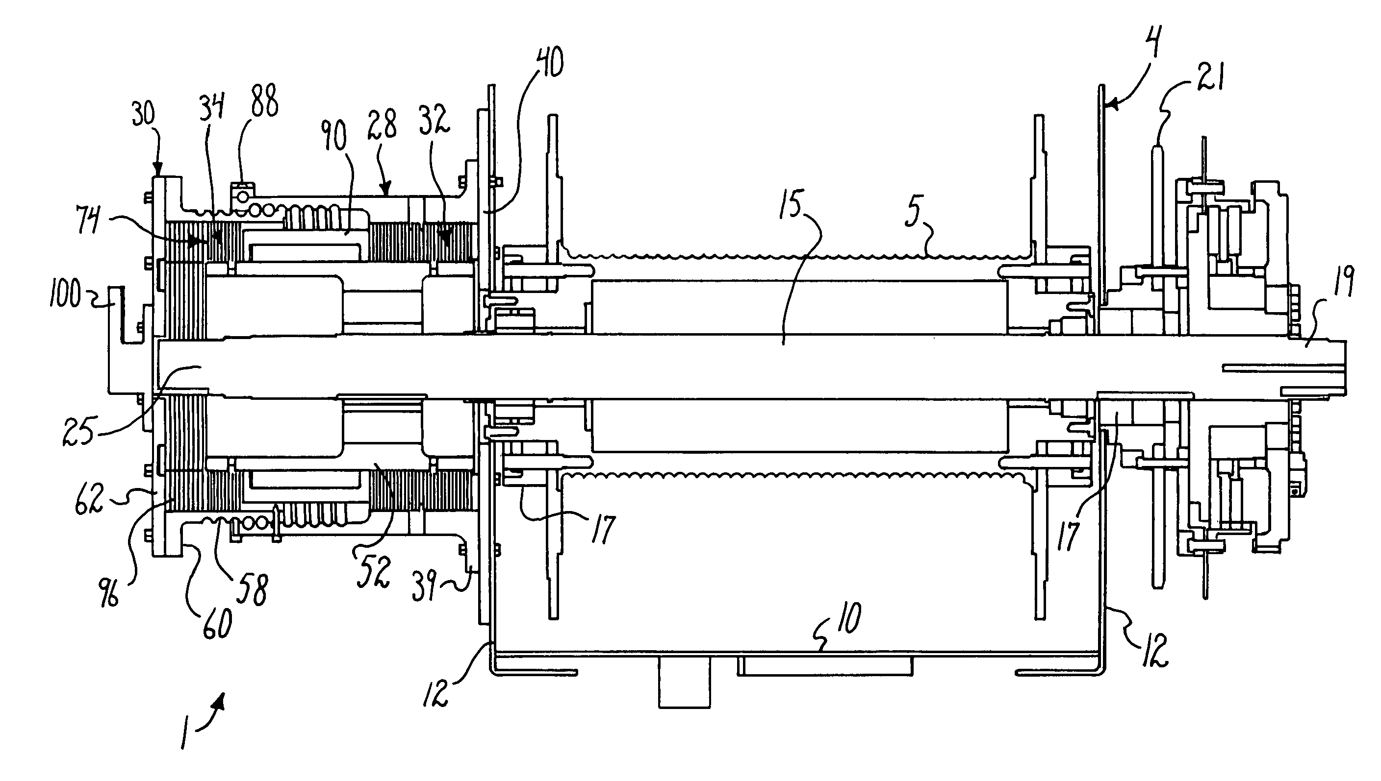
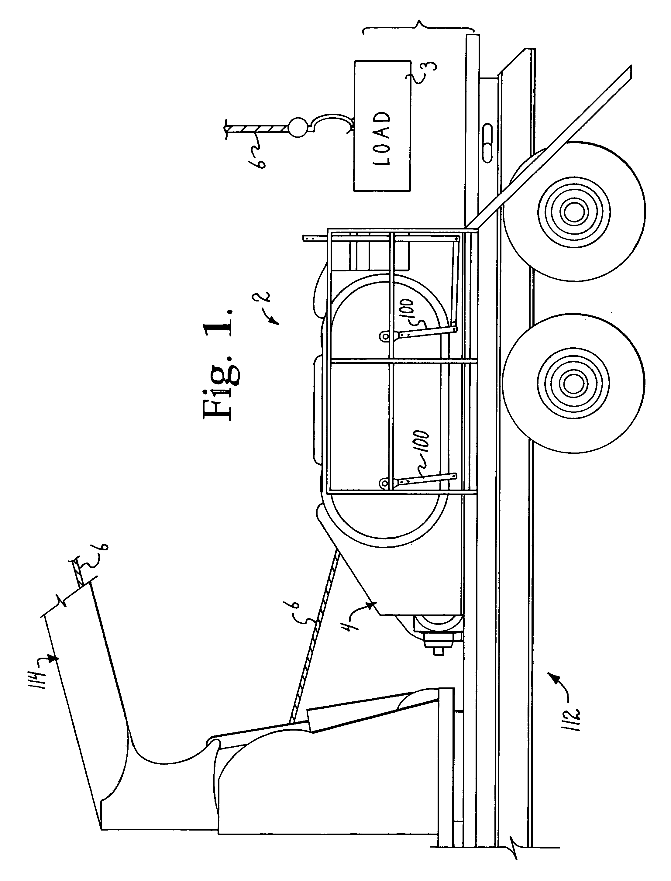
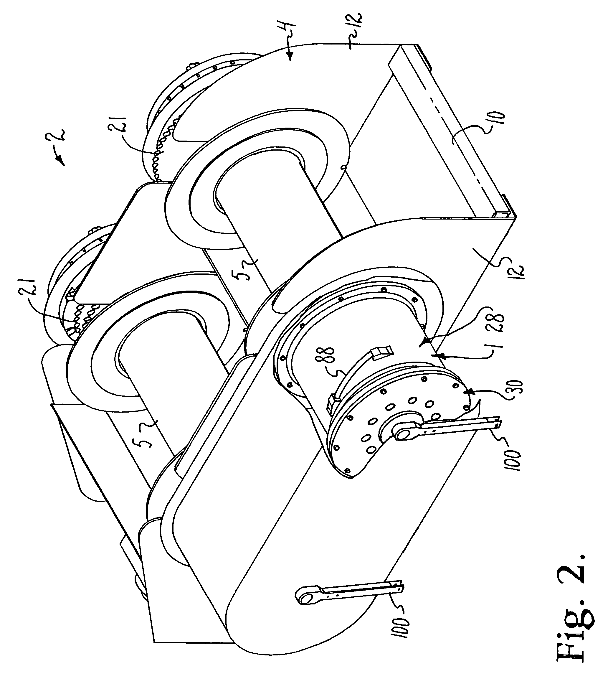
[0029]Referring to the drawings in more detail, the reference numeral 1 (FIGS. 2 and 3) generally designates an embodiment of a fluid shear actuated hoist brake mechanism according to the present invention. In general, the hoist brake mechanism 1 is used in cooperation with hoist equipment 2 to control the lifting and lowering of a load 3 (FIG. 1). The hoist equipment 2 includes a hoist framework 4 on which a cable drum 5 is rotatably mounted and on which a h...


PUM


Abstract

A fluid shear actuated brake mechanism includes an outer hub secured to a hoist frame, a main brake disc stack engaged between the outer hub and a hoist drum shaft, an actuator hub helically engaged with the outer hub, and an actuator disc stack engaged between the actuator hub and the shaft. The main disc stack and the actuator disc stack are immersed in a fluid. Rotation of the shaft in a load lowering direction generates fluid shear in the actuator disc stack which rotates the actuator hub in a lowering direction and advances it toward the main disc stack, compressing it and the actuator disc stack. Rotation of the shaft in an opposite load lift direction retract the actuator hub from the main disc stack.

Description

BACKGROUND OF THE INVENTION[0001]The present invention is broadly concerned with lifting equipment and, more particularly, with a hoist brake mechanism which is actuated by directional fluid shear to control lowering of a heavy load.[0002]Construction and other activities involve the lifting and repositioning of heavy equipment, structural members, building materials, and the like. Hoisting apparatus typically includes a cable drum mounted on a framework, a motor to rotate the cable drum to lift the load, and a brake engaged with the drum shaft to control the lowering and stopping of the load. The hoisting apparatus may be mounted on or connected to a boom which may be swung about to a desired location for lifting or lowering of a load. During lifting, the motor is engaged with the shaft, as by a gearing and / or clutch arrangement, to rotate the shaft and lift the load. When the load reaches its maximum desired height, the brake is applied to halt rotation of the shaft, as the motor ...

Claims


Application Information

Patent Timeline
Patent Type & Authority Patents(United States)
IPC IPC(8): B66D1/14
CPCB66D5/14
Inventor HESS, DANIEL L.
Owner HESS DANIEL L
Why Eureka
Try Eureka