Road milling machine and method for measuring the milling depth

a road milling machine and milling depth technology, which is applied in the direction of slitting machines, roads, constructions, etc., can solve the problems of affecting so as to minimize deviation and improve the accuracy of milling depth measurement

Active Publication Date: 2012-08-21
WIRTGEN AMERICA
View PDF19 Cites 80 Cited by
  • Summary
  • Abstract
  • Description
  • Claims
  • Application Information

AI Technical Summary

Benefits of technology

[0010]It is an object of the present invention to improve the accuracy of measuring the milling depth during the operation of a road milling machine and to thereby minimize deviations from a predetermined milling depth.
[0013]Using the stripping means as a sensor means is advantageous in that no measuring errors are caused by some unevenness in the milling track. It is another advantage that the stripping means is protected against wear at its bottom edge.
[0016]Also for side plates, there is an advantage that their bottom edges are protected against wear.
[0019]Hereby, it can be avoided that a measurement error is caused by using different reference planes for the measurement at the side plates with respect to the measurement at the stripping plate.

Problems solved by technology

It is a problem with known road milling machines that the milling depth can not be controlled accurately enough and that, for this reason, the milling depth has to be measured repeatedly by hand during the milling operation.
Especially in cases where a hard traffic surface, e.g. concrete, is milled, the tools are worn heavily so that the milling depth set is corrupted by the decreasing diameter of the cutting circle.
For example, the wear of the tools, when milling concrete, can cause a difference in the milling radius of 15 mm after only a few 100 m, so that the measuring of an adjustment of side plates, for example, with respect to the machine frame is not sufficiently accurate.
If the milling depth is insufficient, a time-consuming reworking of the milling track has to be carried out.

Method used


Image

  • Road milling machine and method for measuring the milling depth
  • Road milling machine and method for measuring the milling depth
  • Road milling machine and method for measuring the milling depth

Examples


Embodiment Construction

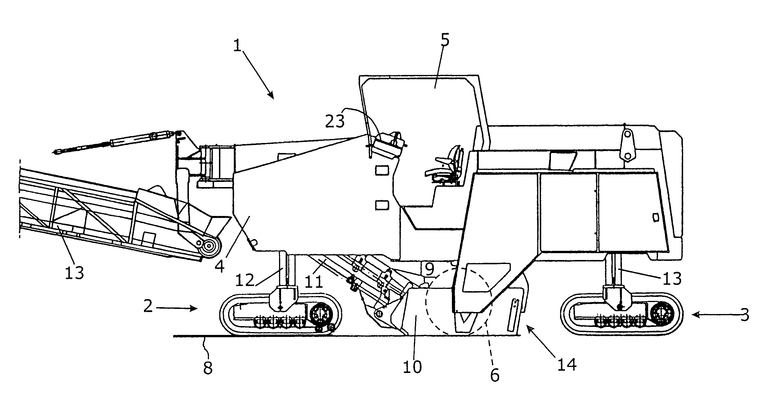
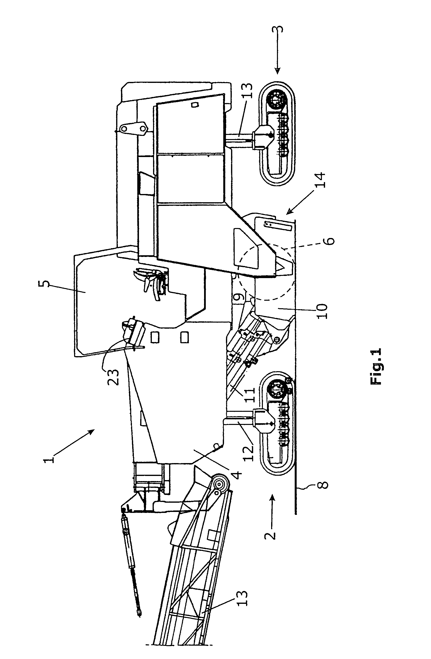
[0039]The road milling machine illustrated in FIG. 1 comprises a machine frame 4 supported by a track assembly having two front chain tracks 2 and at least one rear chain track 3. The chain tracks 2, 3 are connected with the machine frame 4 via lifting columns 12, 13. It is understood that wheels may be used instead of the chain tracks 2, 3.

[0040]Using the lifting columns 12, 13, the machine frame 4 can be lifted or lowered or moved to take a predetermined inclined position with respect to the ground or traffic surface 8. The milling roll 6 supported in the machine frame 4 is enclosed by a roll case 9 which is open at the front, seen in the travelling direction, towards a conveyor belt 11 that conveys the milled material in a front part of the machine frame 4 to a second conveyor means 13. The second conveyor means 13 with which the milled material may be delivered onto a truck, for example, is not fully illustrated in FIG. 1 because of its length. Behind the milling roll 6, a heigh...


PUM


Abstract

In a self-propelling road milling machine (1), particularly a (recycler or) cold-milling machine, comprising a machine frame (4) carried by a track assemblies (2,3) via lifting columns (12,13), a milling roll (6) supported on the machine frame (4) for treatment of a ground or traffic surface (8), height-adjustable side plates (10) for edge protection, arranged to rest on the ground or traffic surface (8) to be treated, a height-adjustable stripping means (14) arranged in the moving direction behind the milling roll (6) and adapted to be lowered, during operation, into the milling track (17) generated by the milling roll (6), and a control means (23) for controlling the milling depth of the milling roller (6), it is provided that at least one measuring means (16) is operative to detect the lifting, caused by the current milling depth, of a first sensor means resting on the ground or traffic surface (8), and / or the lowering of the stripping means (14) or a second sensor means onto the surface of the milling track (17), the control means (23) obtaining the current milling depth at the level of the stripping means (14) of the milling roller (6) or of the second sensor means from the measurement values of the at least one measuring means (16).

Description

BACKGROUND OF THE INVENTION[0001]1. Related Foreign Application[0002]The present application claims the priority of the German Patent Application No. 10 2006 062 129.8 of Dec. 22, 2006, the disclosure of which is herewith incorporated herein by reference.[0003]2. Field of the Invention[0004]The invention refers to a self-propelled road milling machine, especially a cold milling machine, as well as methods for measuring the milling depth.[0005]3. Description of Related Art[0006]With such road milling machines, the machine frame is supported by a track assembly comprising wheels or caterpillar tracks connected to the machine frame through lifting columns, the lifting columns allowing to maintain the machine frame in a horizontal plane or in parallel to the ground or under a predetermined longitudinal and / or transversal inclination.[0007]A milling roll for working a ground or traffic surface is supported at the machine frame.[0008]Near the front end sides of the milling roll height-adj...

Claims


Application Information

Patent Timeline
Patent Type & Authority Patents(United States)
IPC IPC(8): E01C23/07
CPCE01C23/088E01C23/127G01B5/18
Inventor BERNING, CHRISTIANSIMONS, DIETER
Owner WIRTGEN AMERICA
Why Eureka
Try Eureka