
Treatment tool insertion channel of endoscope

a technology of endoscope and insertion channel, which is applied in the field of treatment tool insertion channel of endoscope, can solve the problems of inability to buckle the insertion channel, the supple portion can easily be buckled, and the basic performance of the endoscope is inevitably sacrificed

Inactive Publication Date: 2012-08-21
HOYA CORP
View PDF24 Cites 37 Cited by
  • Summary
  • Abstract
  • Description
  • Claims
  • Application Information

AI Technical Summary

Benefits of technology

The present invention provides an improved treatment tool insertion channel of an endoscope that allows for easier insertion of treatment tools and smaller outer diameter. The channel includes a flexible inner tube, a spiral groove, and at least one coil wound along the bottom of the spiral groove. The channel is designed to be flexible and provide space for elements required for endoscope performance. The at least one coil may be wound along the bottom of the spiral groove and may include an all-range coil and a border coil. The filler used in the spiral groove may include silicon, polyurethane, fluorocarbon, or polyester. The depth and pitch of the spiral groove may be changed between the first and second portions of the channel. These technical improvements make the treatment tool insertion channel easier to use and more efficient in performing medical procedures.

Problems solved by technology

In this regard, however, when the supple portion is merely formed from a supple flexible inner tube, the supple portion can easily be buckled due to an operation of bending the bendable part.
Thereby, basic performance of the endoscope is inevitably sacrificed.
In addition, a metal coil with spring characteristics is wound along a bottom of the spiral groove such that the treatment tool insertion channel cannot be buckled even though the bendable part is repeatedly bent (for example, see Japanese Utility Model Provisional Publication No.
Therefore, there are caused problems that it is difficult to adapt both of the supple portion and the flexible portion in optimum flexibility conditions such that the treatment tool insertion channel is not easily buckled even at a border portion between the supple portion and the flexible portion.

Method used


Image

  • Treatment tool insertion channel of endoscope
  • Treatment tool insertion channel of endoscope
  • Treatment tool insertion channel of endoscope

Examples


first embodiment

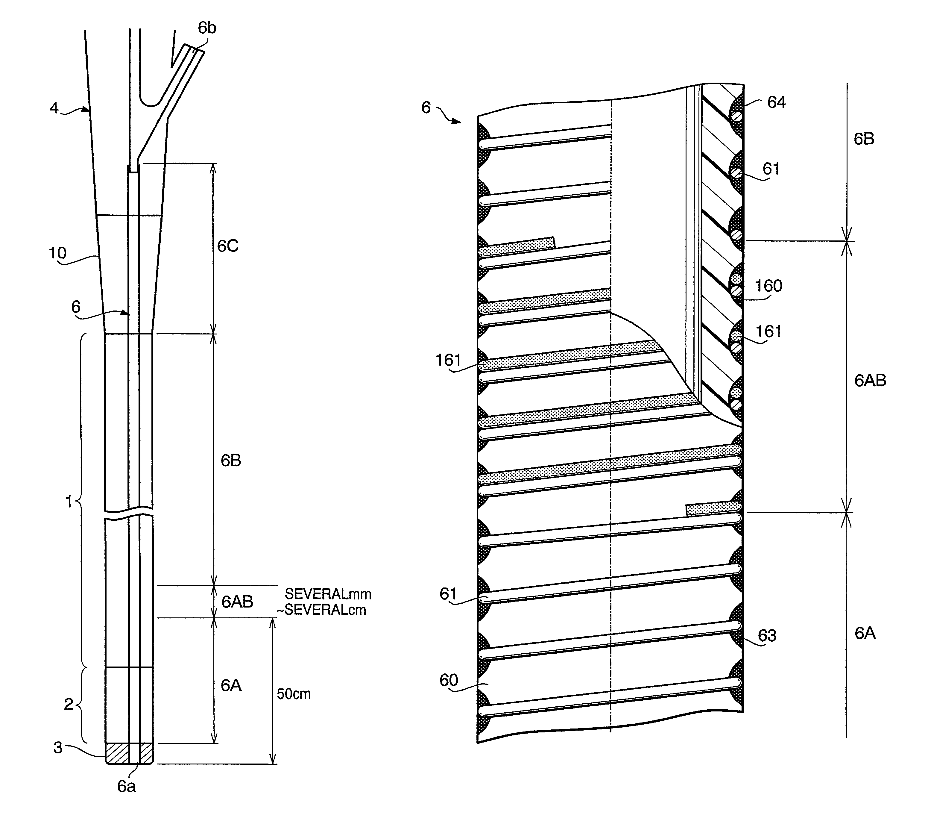
[0038]FIG. 3 shows a concrete configuration of the treatment tool insertion channel 6 in a first embodiment according to the present invention. FIG. 4 is an enlarged view of the border portion 6AB and an area therearound. What is represented by a reference number 60 is a flexible inner tube made from smooth material such as ethylene tetrafluoride resin. There is formed a spiral groove 160 on an outer circumferential surface of the flexible inner tube over an entire range of the supple portion 6A, border portion 6AB, and flexible portion 6B that are located inside the bendable part 2 and the flexible tube 1, so as to attain very flexible characteristics of the relevant portions 6A, 6AB, and 6B. Meanwhile, the spiral groove 160 is not formed around the rigid portion 6C, and therefore the rigid portion 6C is not so flexible.

[0039]It is noted that the spiral groove 160 may concurrently be thermoformed when the flexible tube 60 is formed by extrusion molding, or may be formed by machinin...

fifth embodiment

[0054]The treatment tool insertion channel 6 of the fifth embodiment is configured to have different flexibilities between the supple portion 6A and the bendable portion 6B owing to the spiral groove 160′ of different depths therebetween. That is, the spiral groove 160′ is configured with a depth Qa for the supple portion 6A being formed deeper than a depth Qb for the flexible portion 6B (Qa>Qb). Consequently, the supple portion 6A is more flexible than the bendable portion 6B.

[0055]Thus, since the spiral groove 160′ is formed on the outer circumferential surface of the flexible inner tube 60 around both of the supple portion 6A and the flexible portion 61, mechanical characteristics are not significantly different between the supple portion 6A and the flexible portion 6B. Therefore, the treatment tool insertion channel 6 is hard to be buckled in the border area between the supple portion 6A and the flexible portion 6B. In addition, both of the supple portion 6A and the flexible por...

eighth embodiment

[0061]The border portion 6AB of the eighth embodiment can be formed with at least one of the depth and the pitch of the spiral groove 160′ being gradually changed. Thereby, the treatment tool insertion channel 6 is hard to be buckled because of no drastic flexibility change even in the border portion 6AB between the supple portion 6A and the flexible portion 6B.


PUM


Abstract

A treatment tool insertion channel of an endoscope, which is arranged through an inside of an insertion part that includes a flexible tube and a bendable part, includes a flexible inner tube, a spiral groove formed around the flexible inner tube over an entire length of the bendable part and the flexible tube, at least one coil wound along a bottom of the spiral groove, and at least one type of filler with which the spiral groove is filled. The treatment tool insertion channel includes a first portion that includes a part inside the bendable part and a second portion at a proximal end side of the first portion, the first portion being configured more flexible than the second portion.

Description

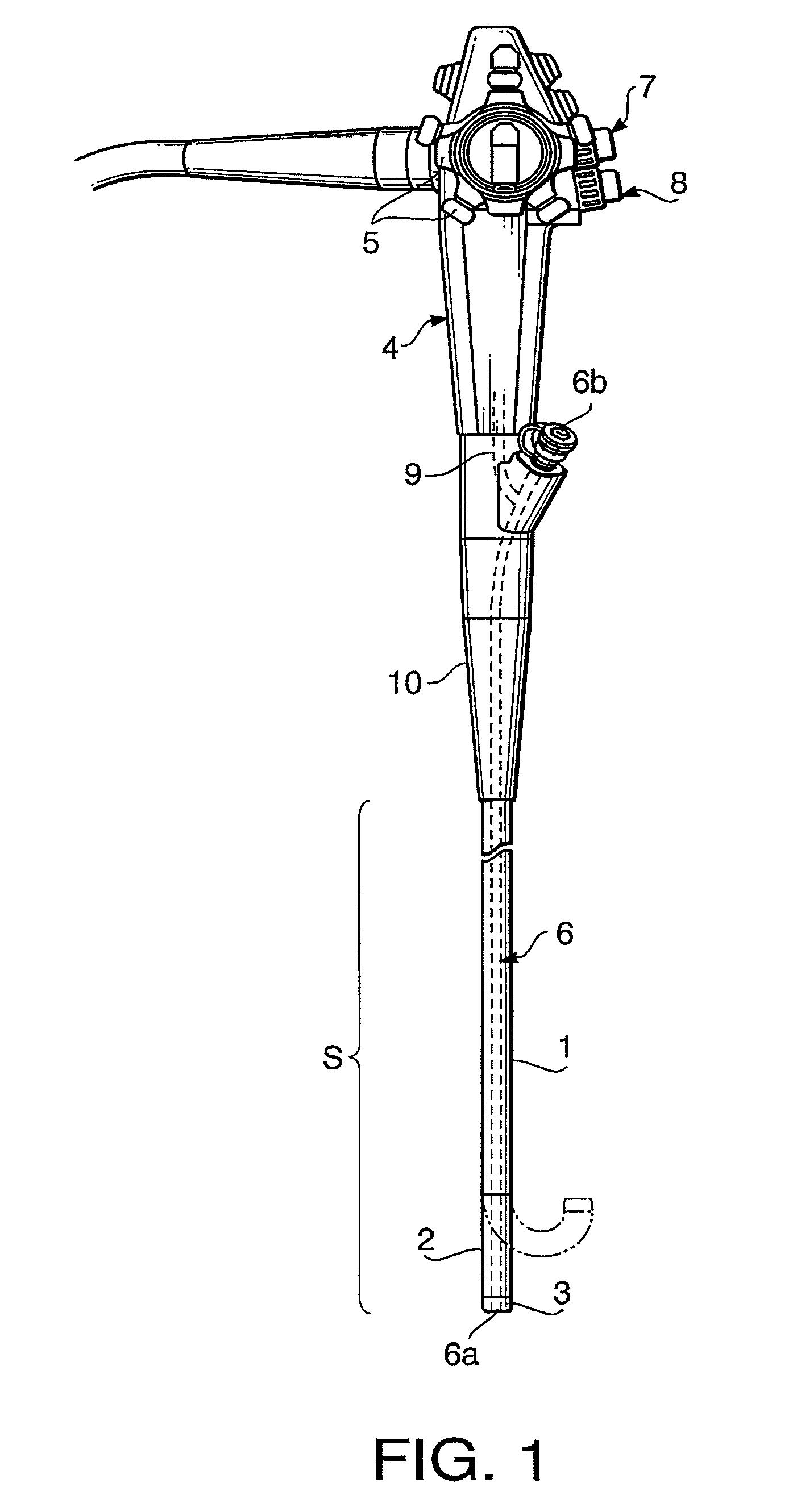
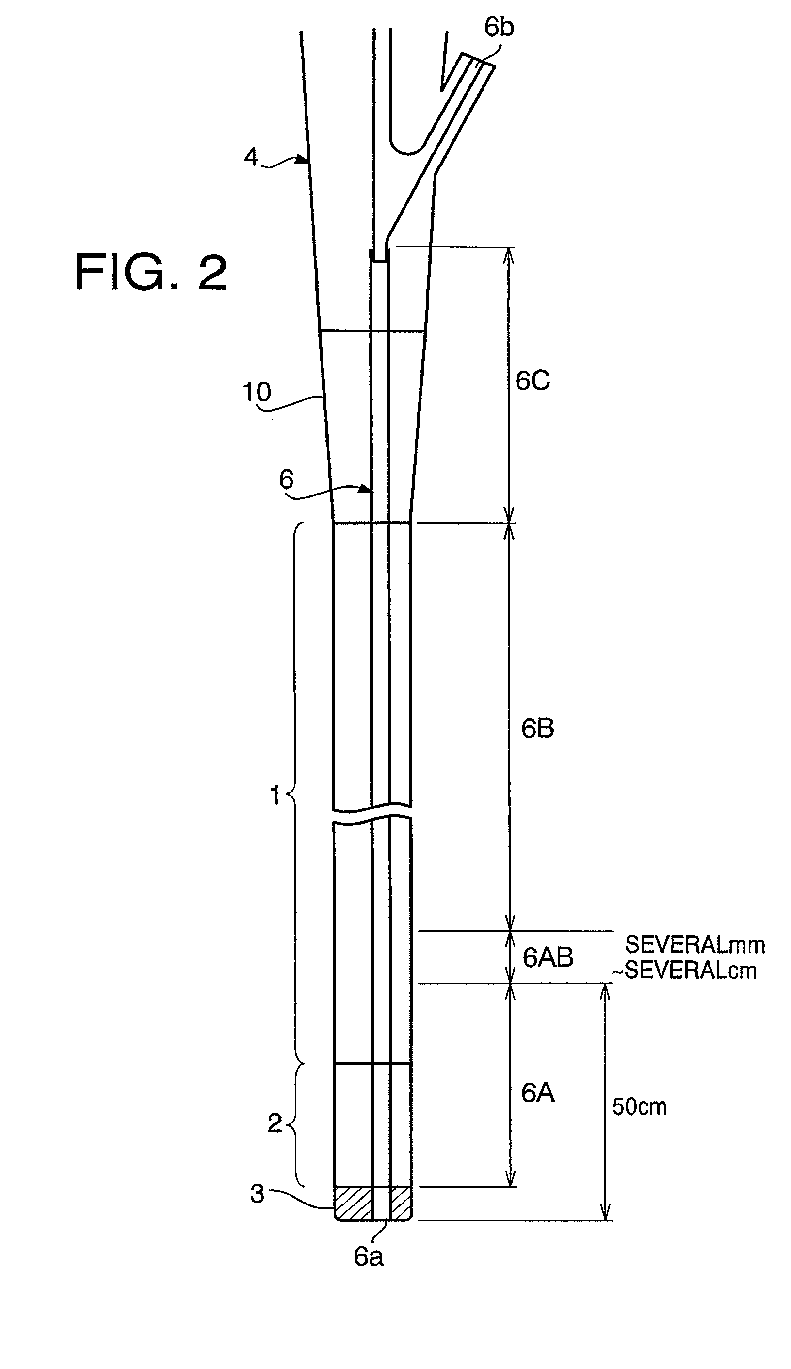
BACKGROUND OF THE INVENTION[0001]The present invention relates to a treatment tool insertion channel of an endoscope.[0002]In general, there are provided to an insertion part of an endoscope a flexible tube and a bendable part linked with a distal end of the flexible tube so as to be bent by a remote control operation. In addition, there are arranged over the entire length of an inner space of the flexible tube and bendable part a treatment tool insertion channel configured such that a treatment tool is inserted thereinto and ejected therefrom.[0003]Further, the treatment tool insertion channel is configured with a front portion (supple portion) thereof that includes an entire part located inside the bendable part being more flexible than a rear portion thereof such that the bendable part can smoothly be bent with a smaller curvature radius by a larger angle than the flexible tube.[0004]In this regard, however, when the supple portion is merely formed from a supple flexible inner tu...

Claims


Application Information

Patent Timeline
Patent Type & Authority Patents(United States)
IPC IPC(8): A61B1/00A61B1/04A61M25/00
CPCA61B1/00071A61B1/0055
Inventor OCHI, KUNITAKAFUJII, YOSHINORITANAKA, NAOKIIWASAKA, KIKUOKANEDA, SATORU
Owner HOYA CORP
Learn More