Two stage plunger for intraocular lens injector

a plunger and intraocular lens technology, applied in the field of ophthalmic surgical devices and methods, can solve the problems of increased risk high care needs to be taken in the handling of the plunger, and highly undesirable surgical outcomes, and achieve the effect of reducing the chance of damage to the iol

Inactive Publication Date: 2012-08-21
BAUSCH & LOMB INC
View PDF90 Cites 37 Cited by
  • Summary
  • Abstract
  • Description
  • Claims
  • Application Information

AI Technical Summary

Benefits of technology

[0007]The present invention provides an improved plunger device and method for inserting an IOL into an eye. In a first aspect of the invention, the plunger of the present invention includes a rigid shaft having a distal tip and a compressible sleeve positioned about the rigid shaft with the distal tip extending forwardly of the uncompressed sleeve. In a first stage of IOL advancement, the plunger distal tip safely engages an IOL positioned within the injector body and advances the IOL for a first distance within the injector body. Preferably, this first distance imparts no or only small compressive forces to the IOL or sleeve. In a second stage of IOL advancement, the compressible sleeve begins compressing about the plunger shaft due to the narrowing walls of the injector body extending toward the open tip thereof. The sleeve compresses and thereby lengthens in a direction toward the distal tip of the plunger shaft. In a preferred embodiment of the invention, the sleeve deforms forwardly and ultimately completely envelops the distal tip of the plunger shaft. Lengthening of the sleeve in a rearward direction is preferably inhibited by a stop feature incorporated into the plunger and / or injector body. The optional but preferred presence of visco-elastic in the injector body is previously applied by the surgeon in an amount sufficient to create hydraulic pressure between the leading edge of the compressed sleeve and the IOL such that the IOL is advanced without direct contact of the optic with the compressed sleeve. As such, the chance of damage to the IOL is reduced, particularly during the critical stage of the IOL being compressed to its smallest diameter.

Problems solved by technology

Since IOLs are very small and delicate articles of manufacture, great care must be taken in their handling.
Should the IOL be damaged during delivery into the eye, the surgeon will most likely need to extract the damaged IOL from the eye and replace it with a new IOL, a highly undesirable surgical outcome.
It will be appreciated that direct contact of the IOL with any injector components increases the risk of damage to the IOL.
Damage to IOL during delivery is many times attributable to the plunger tip which may inadvertently scratch or tear the IOL as it engages and advances the IOL through the injector device.
This latter stage of IOL advancement is therefore a critical stage where forces upon the IOL are at their greatest and the IOL is more susceptible to damage caused by those forces.

Method used


Image

  • Two stage plunger for intraocular lens injector
  • Two stage plunger for intraocular lens injector
  • Two stage plunger for intraocular lens injector

Examples


Embodiment Construction

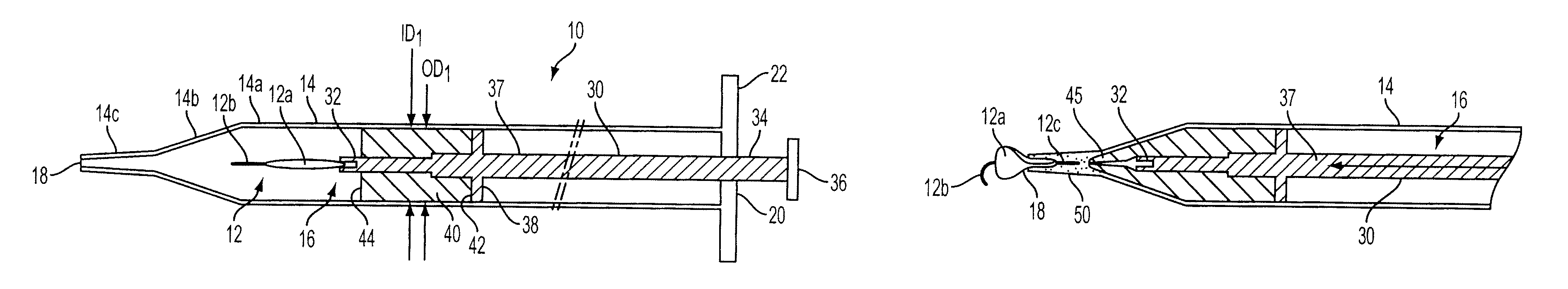
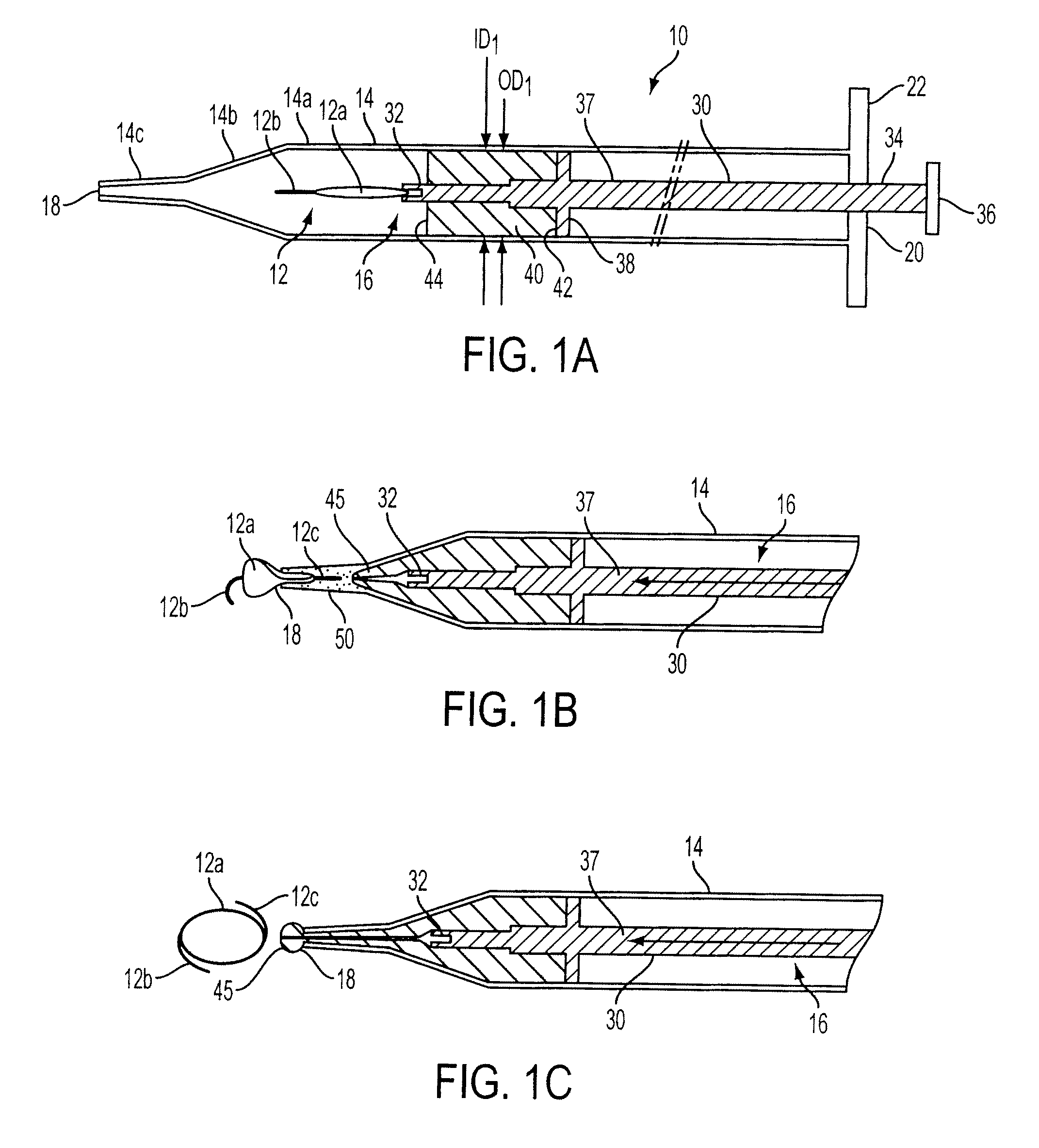
[0011]Referring now to the drawing, there is seen in the various Figures an IOL injector device designated generally by the reference numeral 10. Injector device 10 is used to deliver an IOL 12 into an eye (not shown). The configuration of injector device 10 shown in the Figures is for purposes of description only, it being understood that the injector device 10 may be of any desired configuration such as those employing separate IOL cartridges and / or nozzle tips which are joined to the injector body at the time of surgery (see, for example, U.S. Pat. No. 4,681,102). Still other injector body types may be seen in commonly assigned U.S. Pat. Nos. 5,944,725 and 6,336,932, for example. Injector 10 may furthermore be of the so-called “fully preloaded” or “partially pre-loaded” type wherein the IOL 12 is shipped loaded within the injector device 10, or in a component which is operable to transfer the IOL to the injector device without requiring direct handling of the IOL, respectively (s...


PUM


Abstract

A plunger for an IOL injector device includes a shaft with a distal tip and a compressible sleeve positioned about the shaft with the tip extending forwardly of the sleeve. In a first stage of IOL advancement through the injector device, the plunger tip engages and pushes the IOL through a first section of the injector body. In a second stage of IOL advancement, the sleeve enters the narrowing section of the injector body toward the open tip thereof with the IOL and sleeve both undergoing compression. The sleeve compresses and lengthens in a forward direction ultimately enveloping the plunger distal tip. Viscoelastic applied inside the injector accumulates between the leading edge of the compressed sleeve and the compressed IOL thereby creating hydraulic pressure which pushes the compressed IOL through the remainder of the injector body and out the open distal tip thereof.

Description

BACKGROUND OF THE INVENTION[0001]The present invention relates to ophthalmic surgical devices and methods. More particularly, the present invention relates to a novel plunger device and method for inserting an intraocular lens (hereinafter “IOL”) into an eye.[0002]IOLs are artificial lenses used to replace the natural crystalline lens of the eye when the natural lens has cataracts or is otherwise diseased. IOLs are also sometimes implanted into an eye to correct refractive errors of the eye in which case the natural lens may remain in the eye together with the implanted IOL. The IOL may be placed in either the posterior chamber or anterior chamber of the eye. IOLs come in a variety of configurations and materials. Some common IOL styles include the so-called open-looped haptics which include the three-piece type having an optic and two haptics attached to and extending from the optic; the one-piece type wherein the optic and haptics are integrally formed (e.g., by machining the opti...

Claims


Application Information

Patent Timeline
Patent Type & Authority Patents(United States)
IPC IPC(8): A61F9/007
CPCA61F2/1672A61F9/007A61F9/009A61F9/00A61F2/16
Inventor PYNSON, JOEL
Owner BAUSCH & LOMB INC
Why Eureka
Try Eureka