Device housing a battery and charging pad

a technology for charging pads and devices, which is applied in the direction of mobile unit charging stations, transportation and packaging, and the arrangement of several simultaneous batteries, etc., can solve the problems of inability to accurately determine and the induction coil cannot always be disposed in precise relative positions. , to achieve the effect of accurately determining the position rapid movement of the power supply coil, and accurate determination of the induction coil

Inactive Publication Date: 2012-08-21
SANYO ELECTRIC CO LTD
View PDF13 Cites 27 Cited by
  • Summary
  • Abstract
  • Description
  • Claims
  • Application Information

AI Technical Summary

Benefits of technology

[0008]JP H09-63655 A has the drawback that the battery pack cannot be charged when it is shifted out of proper position on the charging pad. This is because if the position of a mobile electronic device (housing a battery) is shifted relative to the charging pad, the power supply coil and induction coil cannot magnetically couple, and AC power cannot be transmitted from the power supply coil to the induction coil. As described in JP 3011829 U, an alignment projection can be established on the charging pad, and an alignment hole can be provided in the mobile electronic device to insert the alignment projection and reduce position shift between the mobile electronic device and the charging pad. However, even with this structure, the power supply coil and the induction coil cannot always be disposed in precise relative positions.

Problems solved by technology

JP H09-63655 A has the drawback that the battery pack cannot be charged when it is shifted out of proper position on the charging pad.
This is because if the position of a mobile electronic device (housing a battery) is shifted relative to the charging pad, the power supply coil and induction coil cannot magnetically couple, and AC power cannot be transmitted from the power supply coil to the induction coil.
However, even with this structure, the power supply coil and the induction coil cannot always be disposed in precise relative positions.

Method used


Image

  • Device housing a battery and charging pad
  • Device housing a battery and charging pad
  • Device housing a battery and charging pad

Examples


Embodiment Construction

)

[0049]The following describes embodiments of the present invention based on the figures.

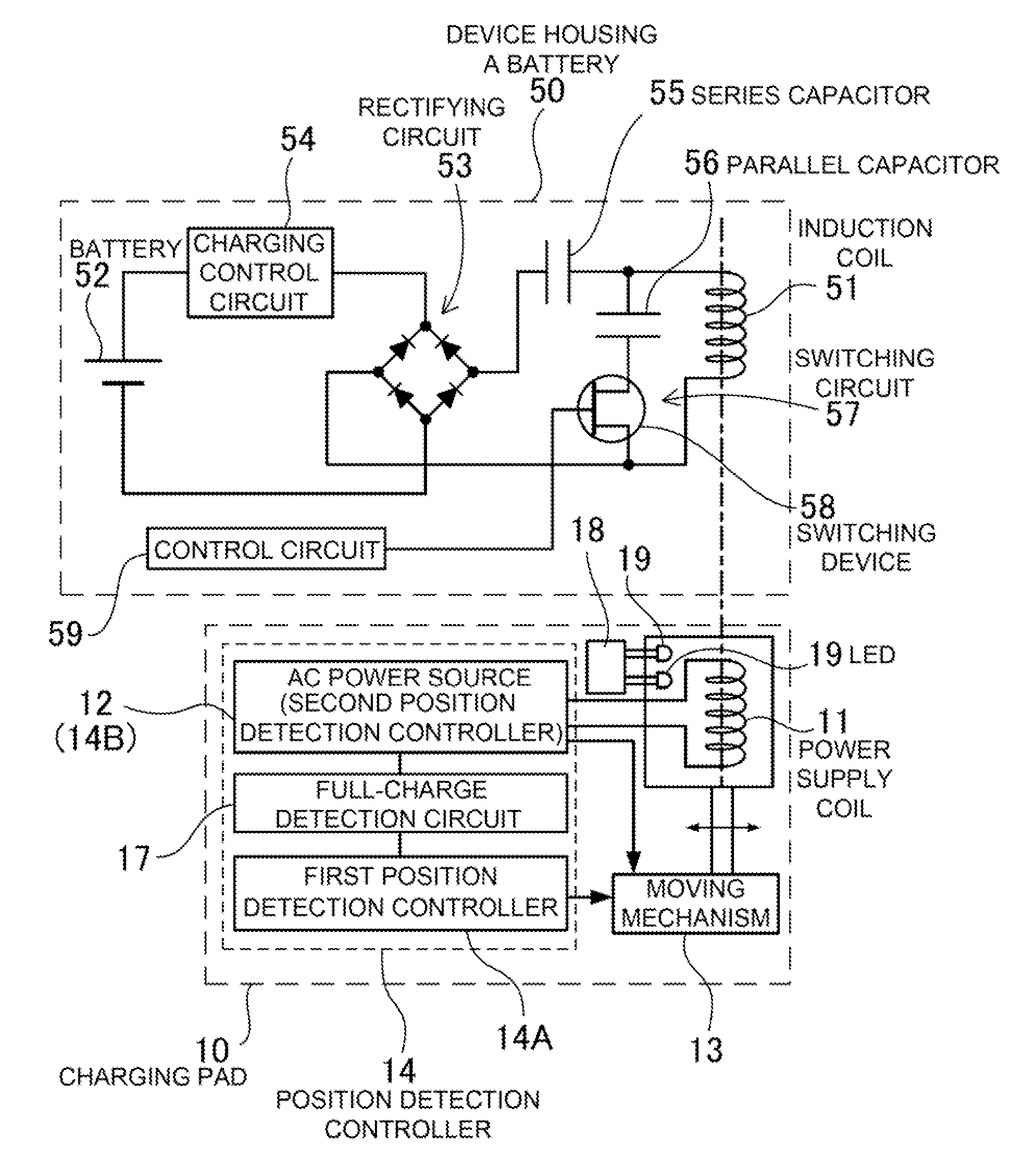
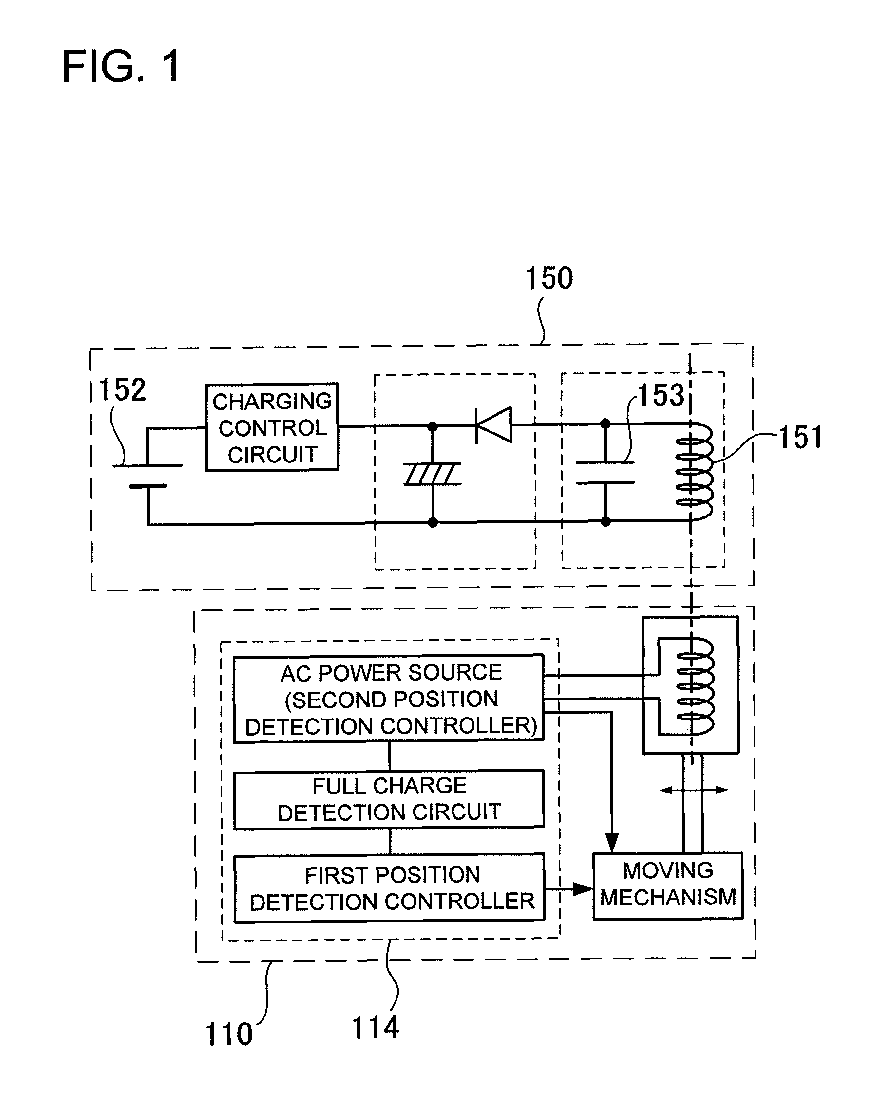
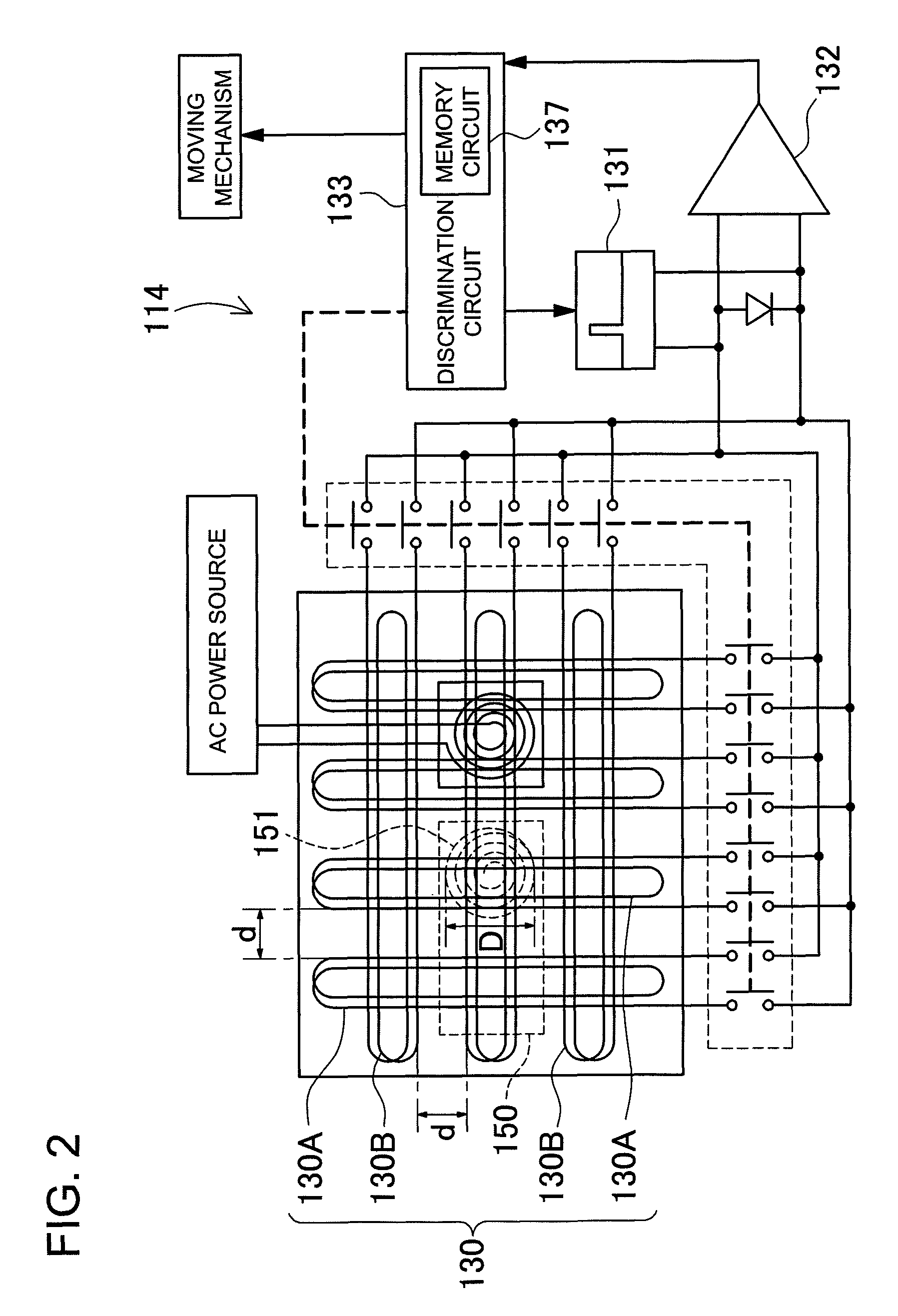
[0050]FIGS. 4-10 are schematic and diagrammatic views illustrating the structure and operating principles of the charging pad 10. As shown in FIGS. 4, 5, and 10, devices housing a battery 50 are placed on the charging pad 10, and the internal battery 52 is charged utilizing magnetic induction. A device housing a battery 50 contains an induction coil 51 that magnetically couples with the power supply coil 11, and a battery 52 that is charged by power induced in the induction coil 51.

[0051]FIGS. 10-12 show circuit diagrams of a device housing a battery 50, 60, 70. The device housing a battery 50, 60, 70 is provided with a rectifying circuit 53 connected to the induction coil 51 that converts AC induced in the induction coil 53 to DC to supply power to the internal battery 52. The rectifying circuit 53 converts AC input from the induction coil 51 to DC and outputs that DC power to a charging contro...


PUM


Abstract

The charging pad 10 is provided with a position detection controller 14 that supplies position detection signals to position detection coils 30, and detects induction coil 51 position from echo signals output from the induction coil 51. The device housing a battery 50 is provided with a series capacitor 55 connected in series with the induction coil 51, a parallel capacitor 56 connected in parallel with the induction coil 51, and a switching circuit 57. When the position detection controller 14 is issuing position detection signals, the parallel capacitor 56 is connected to the induction coil 51. When power is transmitted from the power supply coil 11 to the induction coil 51, the parallel capacitor 56 is not connected to the induction coil 51 and induction coil 51 AC is output to a rectifying circuit 53 through the series capacitor 55.

Description

BACKGROUND OF THE INVENTION[0001]1. Field of the Invention[0002]The present invention relates to a device housing a battery (batteries) such as a battery pack or mobile telephone, and to a charging pad that transmits power by magnetic induction to the device housing a battery to charge the battery inside.[0003]2. Description of the Related Art[0004]A charging pad (charging stand, charging cradle) has been developed to charge a battery housed in a device by transmitting power from a power supply coil (primary coil) to an induction coil (secondary coil) by magnetic induction. (Refer to Japanese Laid-Open Patent Publication HEI 9-63655 (1997) and Utility Model Registration No. 3011829.)[0005]JP H09-63655 A cites a configuration with a charging pad housing a power supply coil driven by an alternating current (AC) power source, and a battery pack housing an induction coil that magnetically couples with the power supply coil. The battery pack houses circuitry to rectify the AC power induc...

Claims


Application Information

Patent Timeline
Patent Type & Authority Patents(United States)
IPC IPC(8): H02J7/00H02J7/02
CPCH02J7/0027H02J7/025H02J7/0042H02J7/0013H02J50/80H02J2310/22H02J50/90H02J50/12H02J50/60H02J50/40
Inventor TOYA, SHOICHITERAO, KYOZO
Owner SANYO ELECTRIC CO LTD
Why Eureka
Try Eureka