Wind turbine tower and method for constructing a wind turbine tower
a wind turbine and wind power technology, applied in the field of wind power tower and wind power tower construction method, can solve the problems of physical limits, and large tower section diameter, so as to reduce the total cost of production, avoid rolling, bending and/or welding, and minimize the total cost of large wind power towers
- Summary
- Abstract
- Description
- Claims
- Application Information
AI Technical Summary
Benefits of technology
Problems solved by technology
Method used
Image
Examples
first embodiment
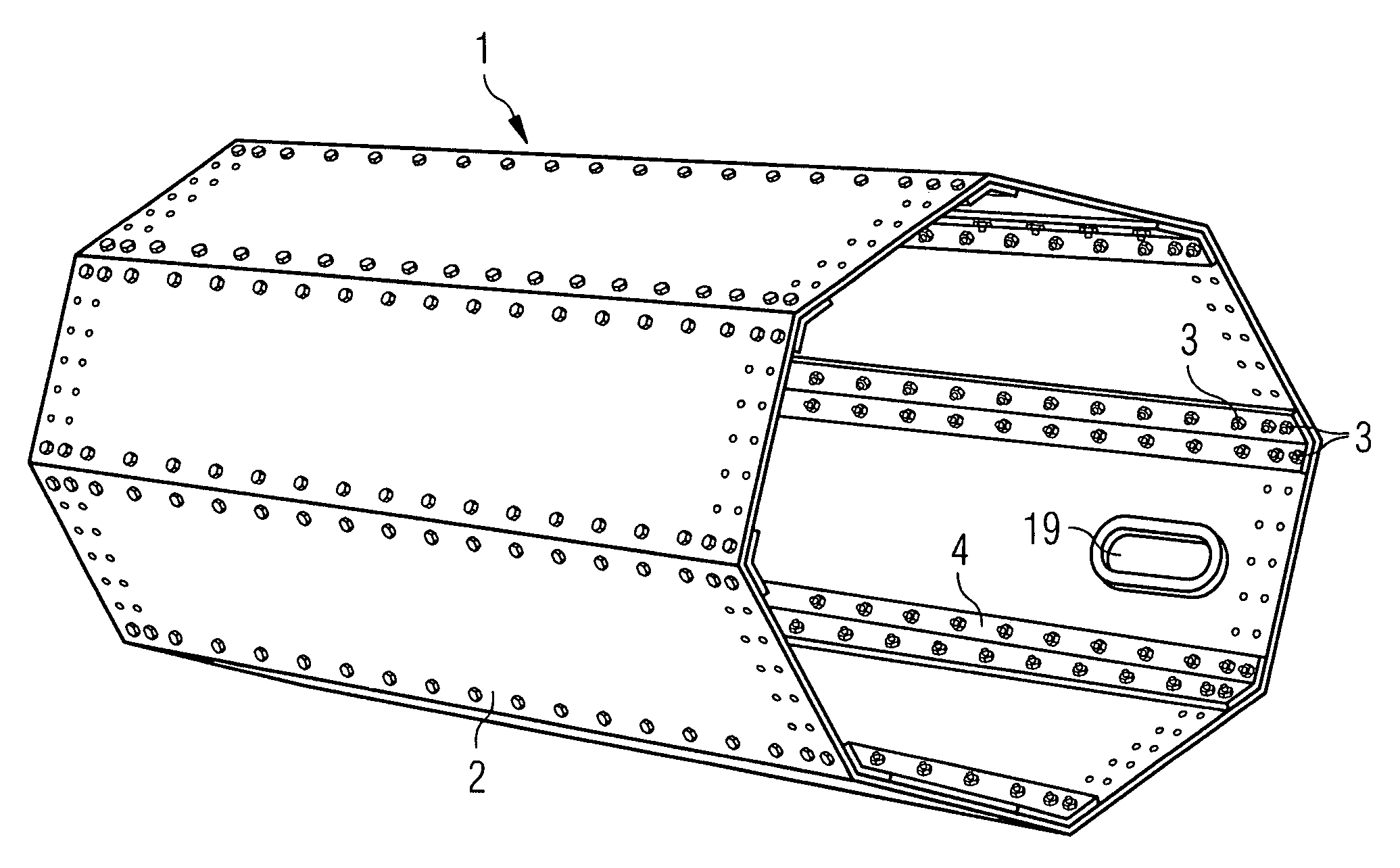
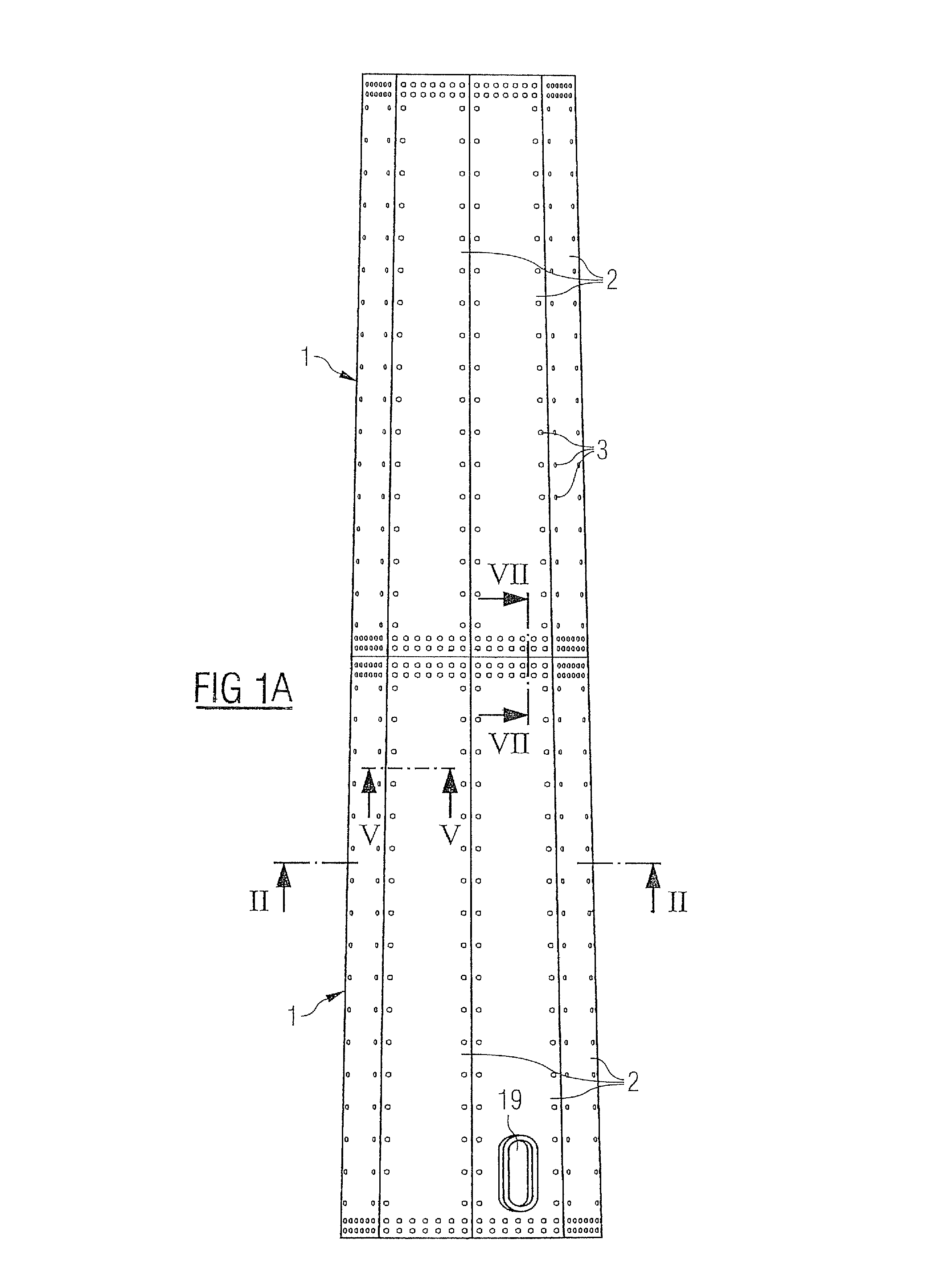
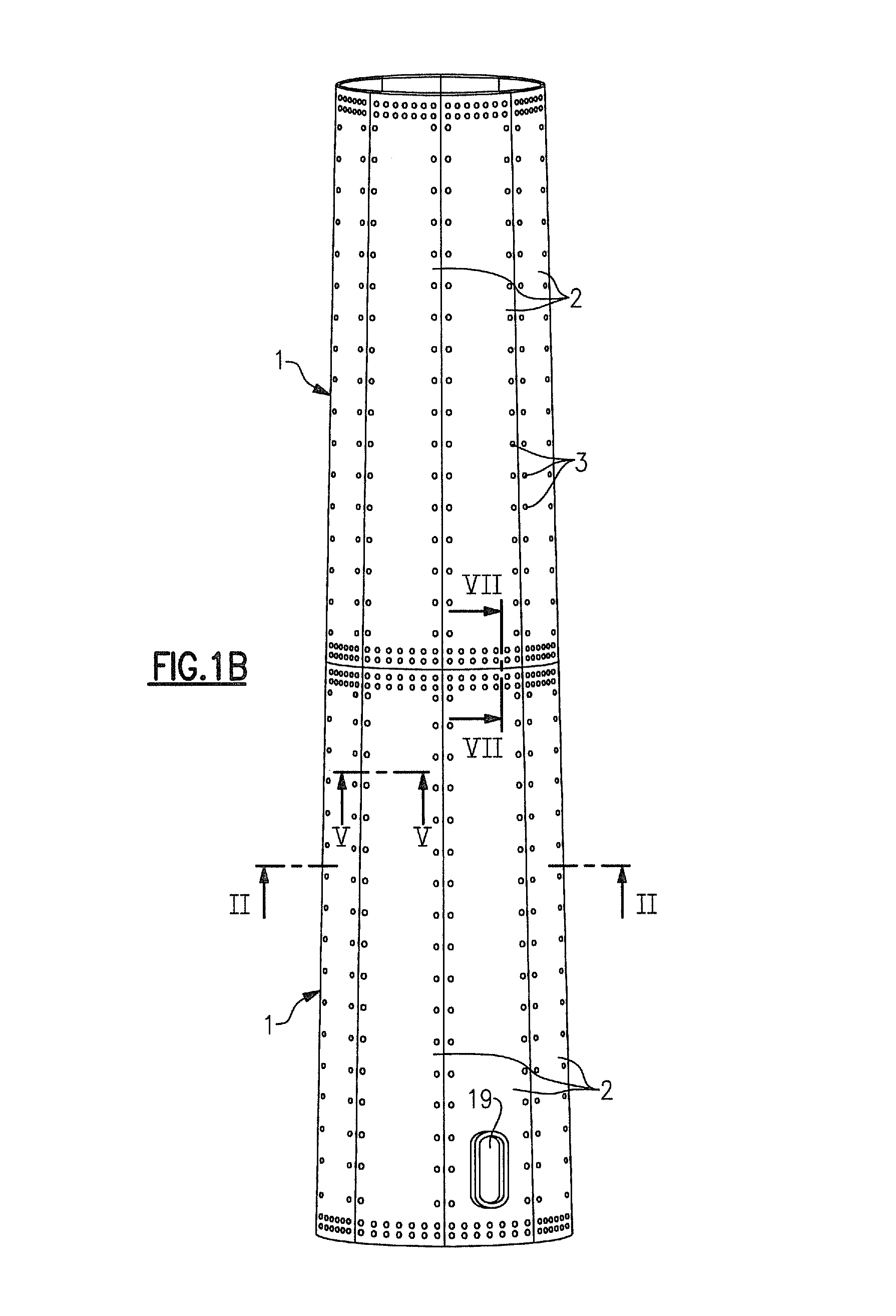
[0042]the inventive wind turbine tower will now be described with respect to FIGS. 1 to 7. FIG. 1 schematically shows part of an inventive wind turbine tower in a frontal view. The wind turbine tower comprises segments 1 which are connected to each other by means of bolts 3 and splice plates. The lowermost segment 1 includes a door 19, a manhole or the like to allow entering the interior of the tower after it is erected.
[0043]Each segment 1 comprises a number of flat plates 2. The flat plates 2 can have a trapezoid shape, as shown in FIG. 1A or, alternatively, a rectangular shape. They can be made of steel or rust resistant steel. Preferably the flat plates 2 have a width of 2.5 to 3 meters and a length of 10 to 14 meters. As an alternative to the flat shape of the flat plates 2 the flat plates 2 can also be corrugated plates. The flat plates 2 are also connected to each other by means of bolts 3 and splice plates. Instead of splice plates or bolts also flanges, nuts, bolt extension...
third embodiment
[0056]In a third embodiment the inventive method for constructing a wind turbine tower will be described with respect to FIGS. 10 to 12. Elements corresponding to elements of the previous embodiments are designated with the same reference numerals and will not be described again to avoid repetition.
[0057]In FIG. 10 an assembly site is sketched which is close to the installation site of an inventive wind turbine tower. One can see in FIG. 10 rails 16 with transport carts 15, a crane 13, a plate storage 14, carriages 10 and a rotation tool 11. At first the delivered flat plates 2 are transported to the installation site by transport carts 15 which is sketched on the right side of FIG. 10. Then the flat plates 2 may be lifted from the transport cart 15 by a crane 13 and stored in a plate storage 14. Instead of a crane 13 any other lifting device may be used, for example a magnet or a vacuum lifting device.
[0058]For assembling a segment 1 the flat plates 2 can be transported by means of...
PUM
 Abstract
Description
Claims
Application Information
 - R&D
- Intellectual Property
- Life Sciences
- Materials
- Tech Scout
- Unparalleled Data Quality
- Higher Quality Content
- 60% Fewer Hallucinations
Browse by: Latest US Patents, China's latest patents, Technical Efficacy Thesaurus, Application Domain, Technology Topic, Popular Technical Reports.
© 2025 PatSnap. All rights reserved.Legal|Privacy policy|Modern Slavery Act Transparency Statement|Sitemap|About US| Contact US: help@patsnap.com


