System and method for calibrating a rotary absolute position sensor

Active Publication Date: 2012-08-28
GM GLOBAL TECH OPERATIONS LLC +1
View PDF5 Cites 12 Cited by
  • Summary
  • Abstract
  • Description
  • Claims
  • Application Information

AI Technical Summary

Problems solved by technology

Proper calibration of a RAP sensor is required due to the inherent imprecision or error in determining an absolute position or angular state of a rotary actuator, e.g., due to errors or noise, sensor mounting imprecision, analog-to-digital (A-to-D) conversion errors, or other factors.

Method used


Image

  • System and method for calibrating a rotary absolute position sensor
  • System and method for calibrating a rotary absolute position sensor
  • System and method for calibrating a rotary absolute position sensor

Examples


Embodiment Construction

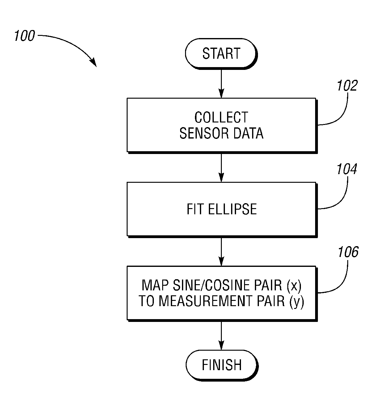
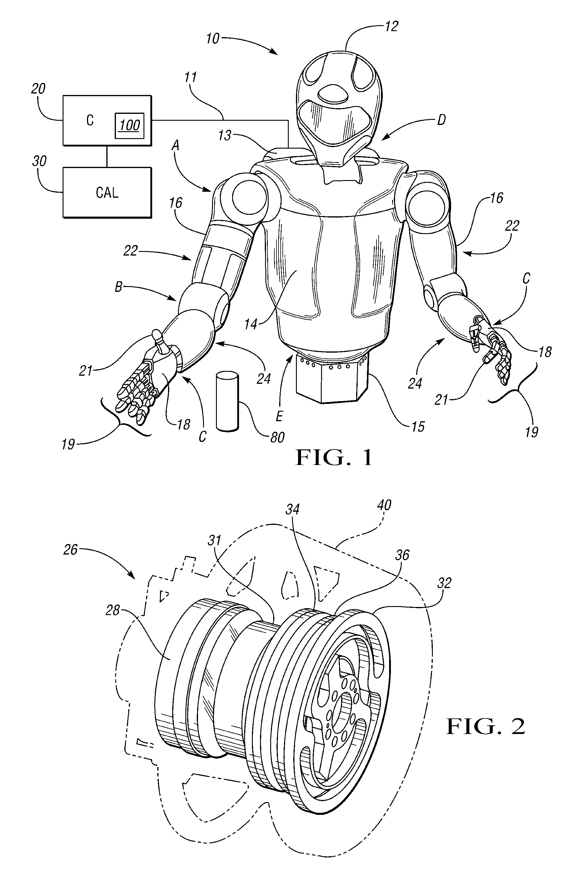
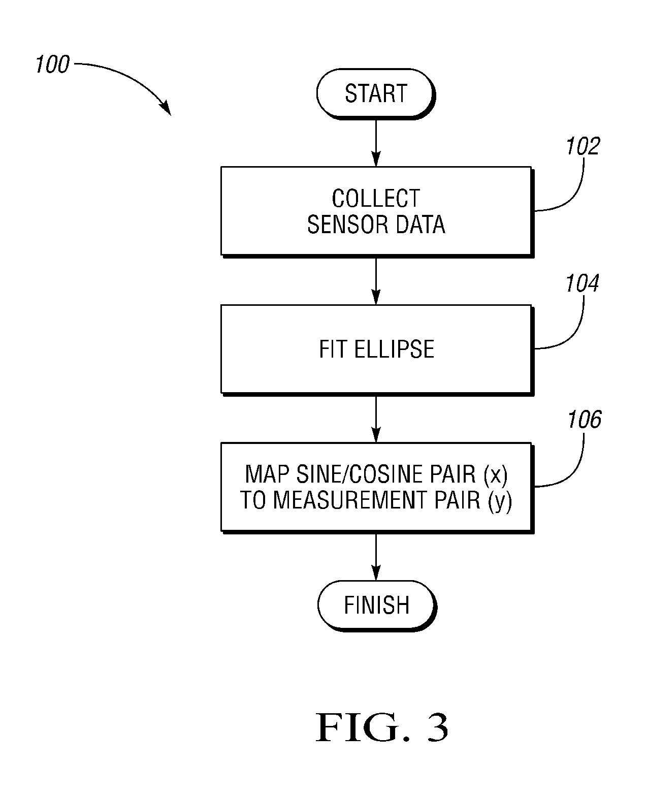
[0016]With reference to the drawings, wherein like reference numbers refer to the same or similar components throughout the several views, FIG. 1 shows a dexterous humanoid robot 10 controllable via a distributed control system or controller (C) 20. The robot 10 includes one or more rotary devices, e.g., motors, links, etc., which in one embodiment are configured as part of a series elastic actuator (SEA) 26 (see FIG. 2). However, any rotary device may be used in conjunction with the method described herein. The rotary device may be part of a highly complex robotic system of the type shown in FIG. 1, or part of a simple or base-level system, as will be understood by those of ordinary skill in the art.

[0017]The robot 10 is adapted to perform one or more autonomous tasks with multiple degrees of freedom (DOF). According to one embodiment, the robot 10 is configured with a plurality of independently and interdependently-moveable compliant robotic joints, such as but not limited to a sh...


PUM


Abstract

A system includes a rotary device, a rotary absolute position (RAP) sensor generating encoded pairs of voltage signals describing positional data of the rotary device, a host machine, and an algorithm. The algorithm calculates calibration parameters usable to determine an absolute position of the rotary device using the encoded pairs, and is adapted for linearly-mapping an ellipse defined by the encoded pairs to thereby calculate the calibration parameters. A method of calibrating the RAP sensor includes measuring the rotary position as encoded pairs of voltage signals, linearly-mapping an ellipse defined by the encoded pairs to thereby calculate the calibration parameters, and calculating an absolute position of the rotary device using the calibration parameters. The calibration parameters include a positive definite matrix (A) and a center point (q) of the ellipse. The voltage signals may include an encoded sine and cosine of a rotary angle of the rotary device.

Description

STATEMENT REGARDING FEDERALLY SPONSORED RESEARCH OR DEVELOPMENT[0001]This invention was made with government support under NASA Space Act Agreement number SAA-AT-07-003. The government may have certain rights in the invention.TECHNICAL FIELD[0002]The present invention relates to a system and a method for calibrating an absolute position sensor for a rotary actuator or other rotary device.BACKGROUND OF THE INVENTION[0003]Robots are automated or autonomous devices that are able to manipulate objects using a series of links, which in turn are interconnected via articulations or compliant robotic joints. Each joint in a typical robot represents an independent control variable, also referred to as a degree of freedom (DOF). End-effectors are the particular links used for performing a task at hand, e.g., grasping a work tool or other object. Therefore, precise motion control of a robot may be organized by the level of task specification: object level control, i.e., the ability to control ...

Claims


Application Information

Patent Timeline
Patent Type & Authority Patents(United States)
IPC IPC(8): G01C17/38
CPCB25J9/1692G01D5/2449G05B2219/34136
Inventor DAVIS, DONALD R.PERMENTER, FRANK NOBLERADFORD, NICOLAUS A
Owner GM GLOBAL TECH OPERATIONS LLC
Why Eureka
Try Eureka