
Multi-axis force sensor and acceleration sensor

a multi-axis force sensor and acceleration sensor technology, applied in the direction of acceleration measurement using interia force, force/torque/work measurement apparatus, instruments, etc., can solve the problem of adverse effects on detection precision, and achieve the effect of improving detection precision and reducing nois

Active Publication Date: 2012-08-28
HONDA MOTOR CO LTD
View PDF42 Cites 27 Cited by
  • Summary
  • Abstract
  • Description
  • Claims
  • Application Information

AI Technical Summary

Benefits of technology

The present invention provides a multi-axis force sensor and an acceleration sensor that can improve detection precision by cancelling out noises in the Z-axis direction. This is achieved by using a first bridge circuit group and a second bridge circuit group to detect strain caused by the external force. The first group of strain resistance elements and the second group of strain resistance elements produce positive and negative voltages when they receive tensile or compressive force, and the first and second bridge circuit groups output opposite polarities to each other. This cancellation of noises helps to improve the detection precision of the force components in X-axis and Y-axis directions. The first group of strain resistance elements may be composed of a p-type semiconductor strain gauge and a n-type semiconductor strain gauge, and the second group of strain resistance elements may be built in the ground side or voltage-output side of the first bridge circuit groups.

Problems solved by technology

In the conventional multi-axis force sensors, however, regarding a force component Fz in a Z-axis direction, because noise components (common-mode noises) contained in a plurality of strain detecting elements are all superimposed and calculated, the detection precision is adversely affected.

Method used


Image

  • Multi-axis force sensor and acceleration sensor
  • Multi-axis force sensor and acceleration sensor
  • Multi-axis force sensor and acceleration sensor

Examples


Embodiment Construction

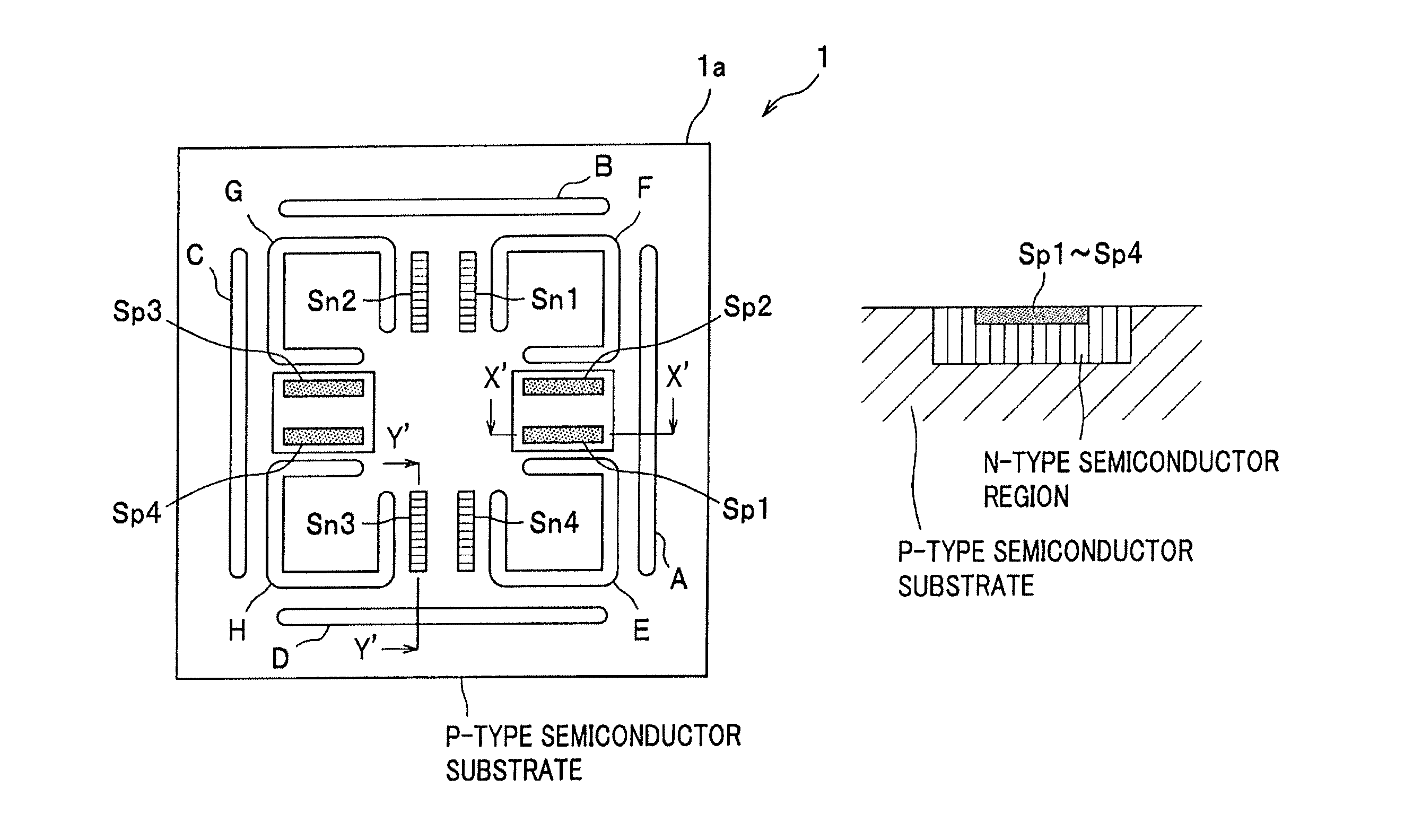
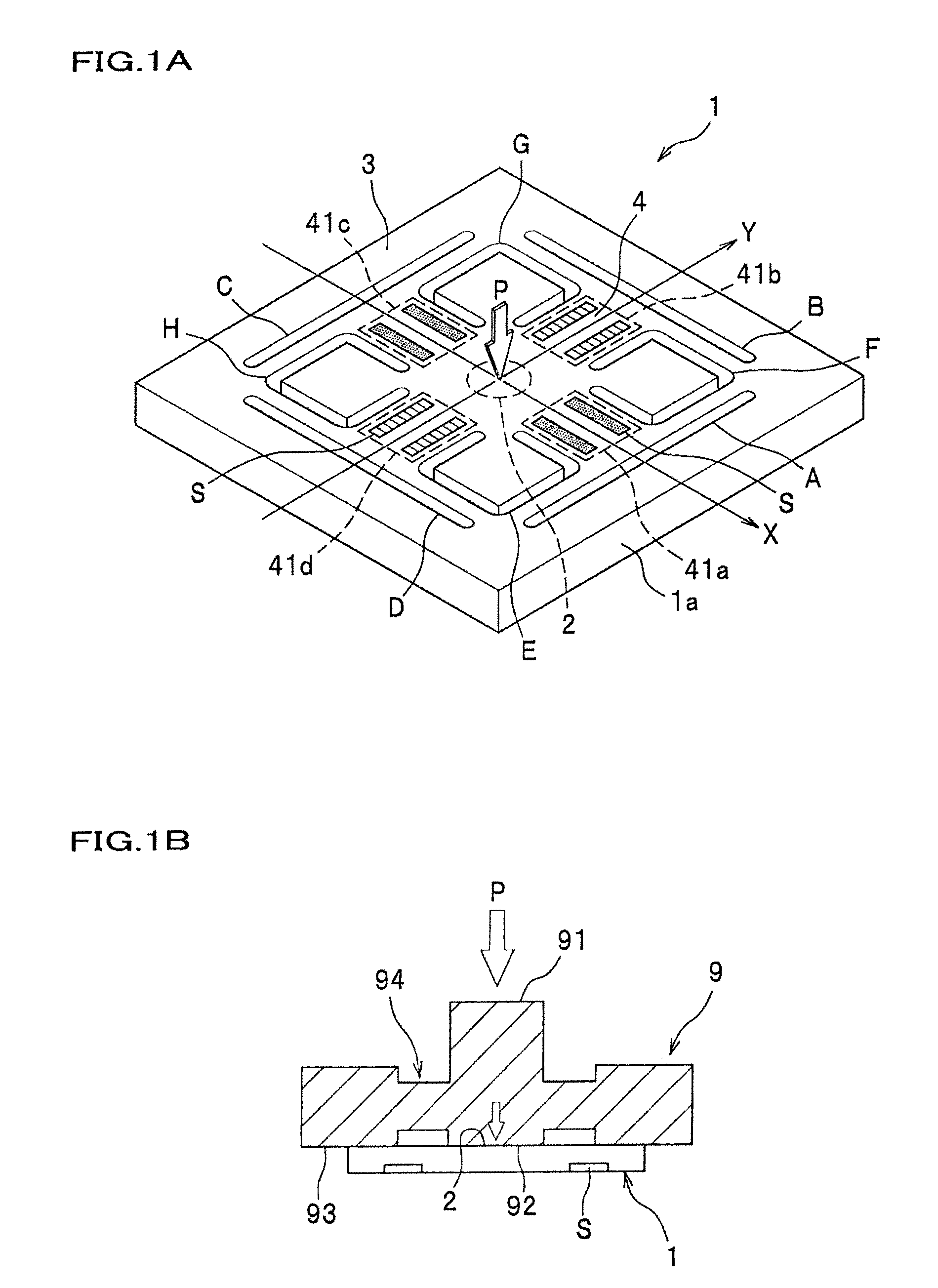
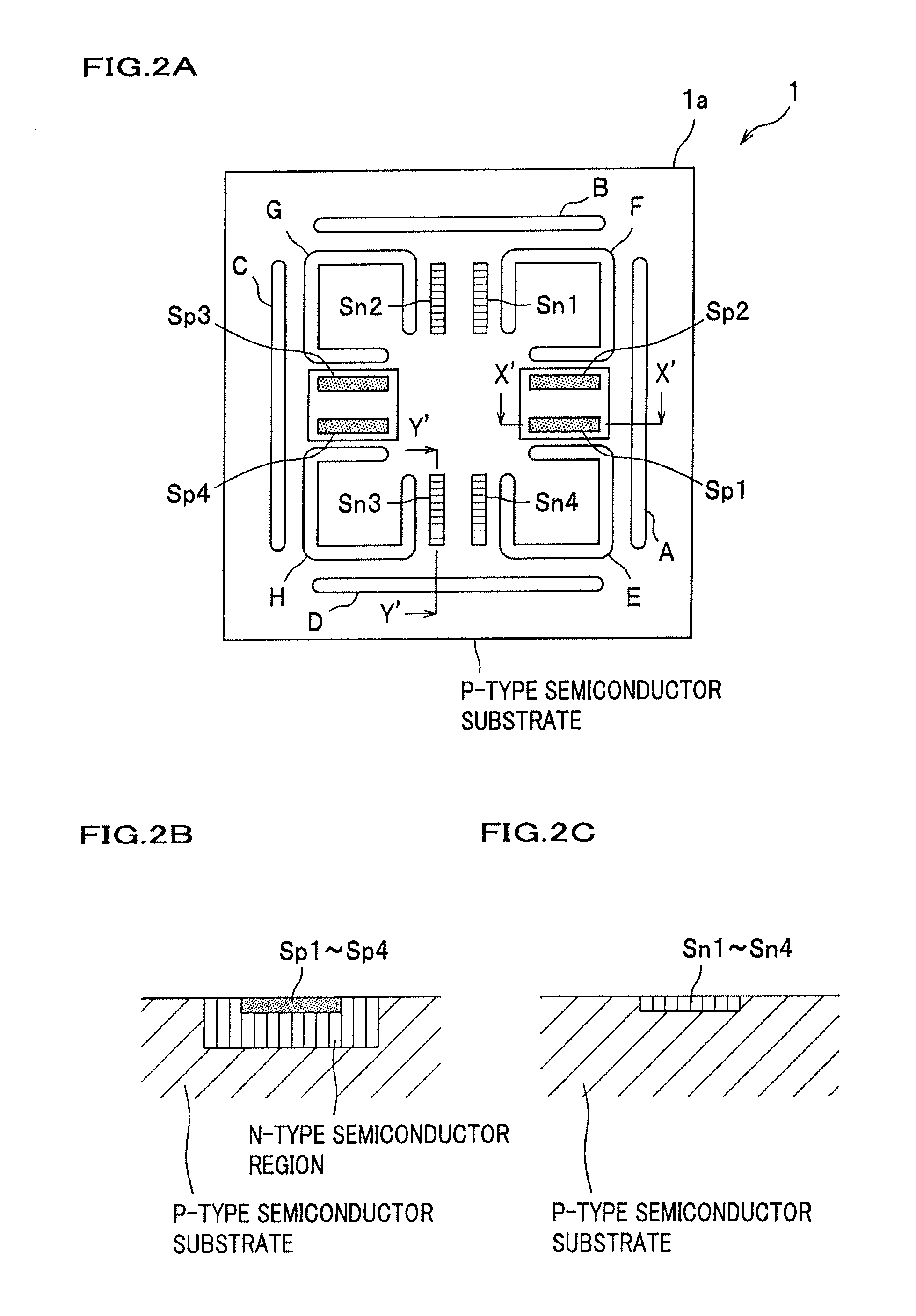
[0028]With reference to FIGS. 1-3, an overall structure of a multi-axis force sensor 1 according to an embodiment of the present invention will be explained in detail. In addition, the accompanying drawings exemplary show main structural elements for convenience of the explanation, and illustration of additional structural elements, such as a wiring, and an electrode, are omitted in the drawings.

[0029]As shown in FIGS. 1A and 2A, the multi-axis force sensor 1 according to the first embodiment of the present invention includes an action portion 2 which is formed on a semiconductor substrate 1a having a substantially-rectangular and flat shape in a planar view, and to which external force P is applied, a support portion 3 which supports the action portion 2, connection portions 4 which connect the support portion 3 to the action portion 2, and strain producing portions 41 which are formed at respective support portions 3 and generate a strain originating from the external force P.

[003...


PUM

PropertyMeasurementUnit
external forceaaaaaaaaaa
strain resistanceaaaaaaaaaa
resistancesaaaaaaaaaa

Abstract

There is provided a multi-axis force sensor including first and second bridge circuit groups detecting resistances of respective first and second groups of strain resistance elements provided at respective strain producing portions. The strain producing portions are formed on two axes intersecting with respect to each other at a right angle. The first group of strain resistance elements are arranged on one axis across an action portion so as to face with respect to each other, and the second group of strain resistance elements are arranged on another axis across the action portion so as to face with respect to each other. The first bridge circuit groups respectively output a positive voltage when receiving tensile force, and the second bridge circuit groups respectively output a negative voltage when receiving tensile force.

Description

CROSS REFERENCE TO RELATED APPLICATION[0001]The present application claims benefit of the filing date of Japanese Patent Application No. 2009-029110 filed on Feb. 10, 2009 which is incorporated herein by reference.BACKGROUND OF THE INVENTION[0002]1. Field of the Invention[0003]The present invention relates to a multi-axis force sensor and an acceleration sensor, and more specifically, to a multi-axis force sensor and an acceleration sensor which cancel noise of a force component in a Z-axis direction.[0004]2. Description of the Related Art[0005]Conventionally, in the field of pressure sensors, there are known pressure sensors having a semiconductor strain gauge (a diffusion gauge) formed on a surface of a diaphragm that is formed on a silicon substrate (see, for example, JP 09-232595 A). In such pressure sensors, four diffusion gauges configure one bridge circuit, and change respective resistances in a positive / negative direction relative to tensile stress. For this reason, it is po...

Claims


Application Information

Patent Timeline
Patent Type & Authority Patents(United States)
IPC IPC(8): G01L1/22G01L5/16G01P15/12G01P15/18H01L29/84
CPCG01L5/161G01P15/123G01P15/18G01L5/162G01P2015/0842G01L5/1627
Inventor SAKURAI, NOBUHIRO
Owner HONDA MOTOR CO LTD
Learn More