
Steering unit for a steer-by-wire ship's control system and method for operating the steering unit

a technology of control system and steering unit, which is applied in the direction of steering initiation, vessel construction, instruments, etc., can solve the problems of inability to add rotational movement in the same direction, poor dynamics, and high maintenance costs, and achieve low rpm, high dynamic response, and large torque

Active Publication Date: 2012-08-28
ZF FRIEDRICHSHAFEN AG
View PDF46 Cites 2 Cited by
  • Summary
  • Abstract
  • Description
  • Claims
  • Application Information

AI Technical Summary

Benefits of technology

[0010]It is the object of the present invention to specify a steering unit for a steer-by-wire ship control system which has a compact design and is easily produced. Furthermore, the steering unit should be highly dynamic. In addition, a method for operation of the steering unit that increases the dependability and ease of use is to be specified.
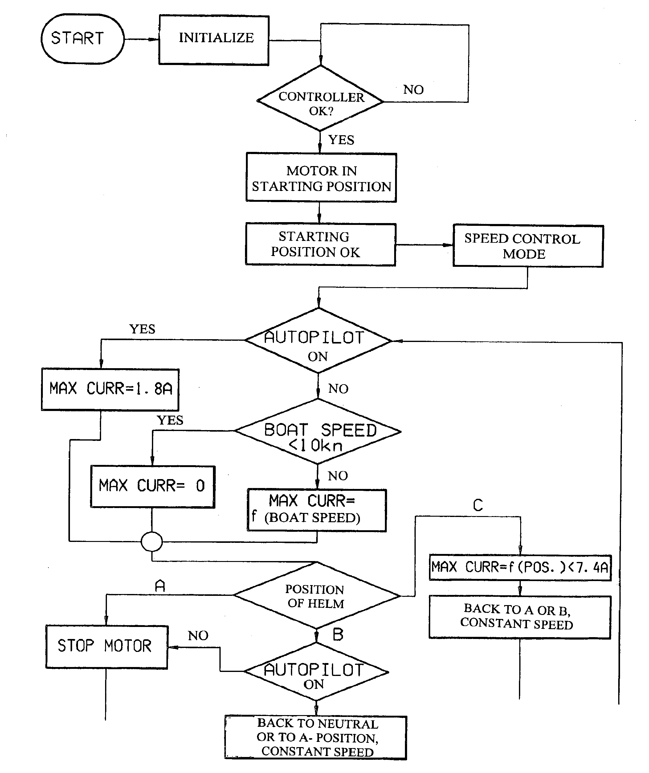
[0014]According to a particularly favorable embodiment of the invention, the electric motor is designed as a vector-controlled, brushless torque motor. This results in a compact design, large torques at low RPM, high dynamic response and minimal circumferential backlash. According to the invention, the torque motor is designed so that it generates a constant torque across the speed range, so that there is no need to install reduction gears. A motor of this kind can be overloaded, in a favorable manner, by 100% for a period of 5 seconds; by comparison, a hydraulic system can be overloaded only by 20%.

Problems solved by technology

In ship control engineering, the steering units connected to the helm are usually hydraulically actuated, which has the adverse result of poor dynamics as well as high maintenance costs.
Once an end position is reached, the mechanical resistance on the helm is adjusted such that an additional rotational movement thereof in the same direction is not possible.

Method used


Image

  • Steering unit for a steer-by-wire ship's control system and method for operating the steering unit
  • Steering unit for a steer-by-wire ship's control system and method for operating the steering unit
  • Steering unit for a steer-by-wire ship's control system and method for operating the steering unit

Examples


Embodiment Construction

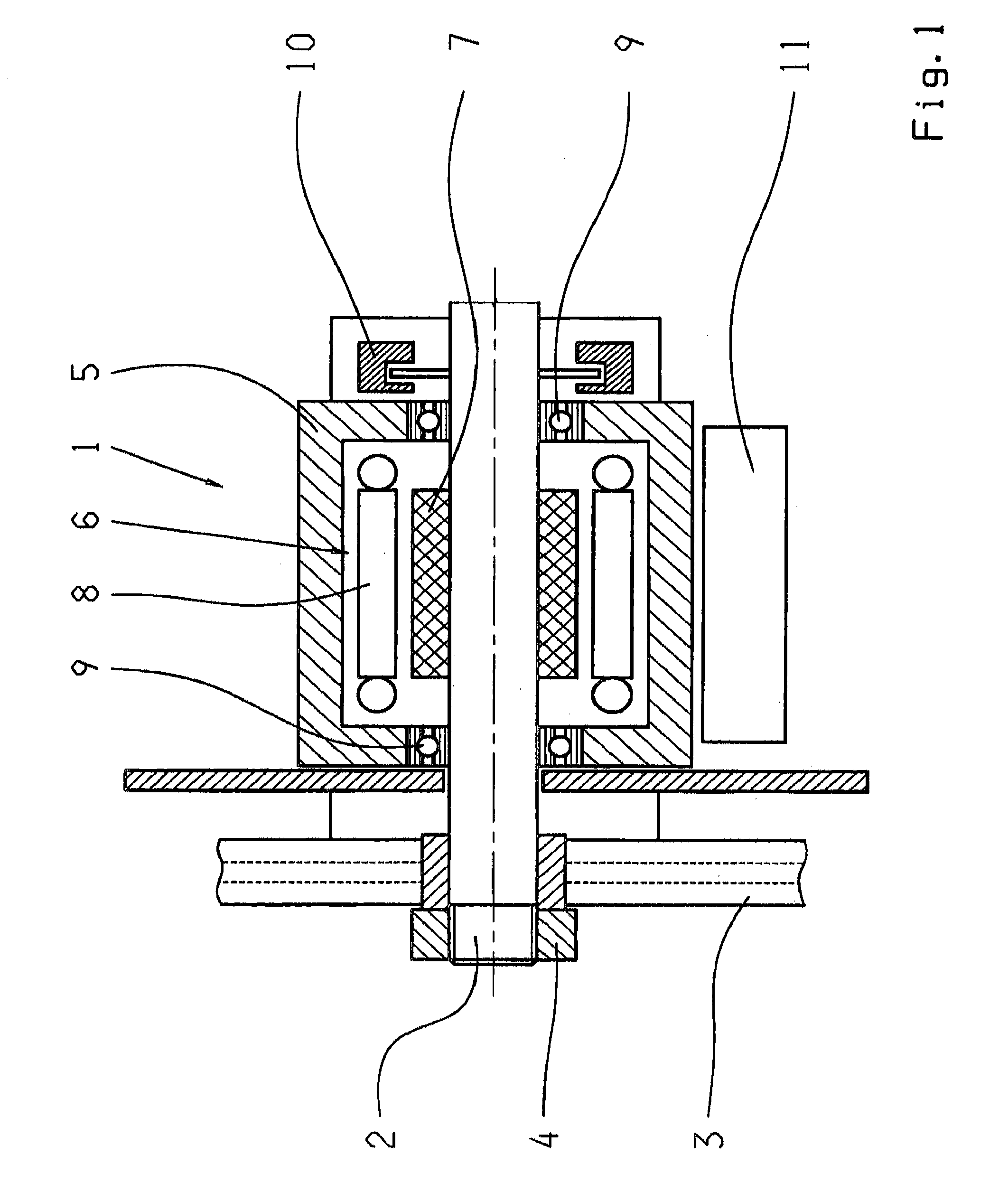
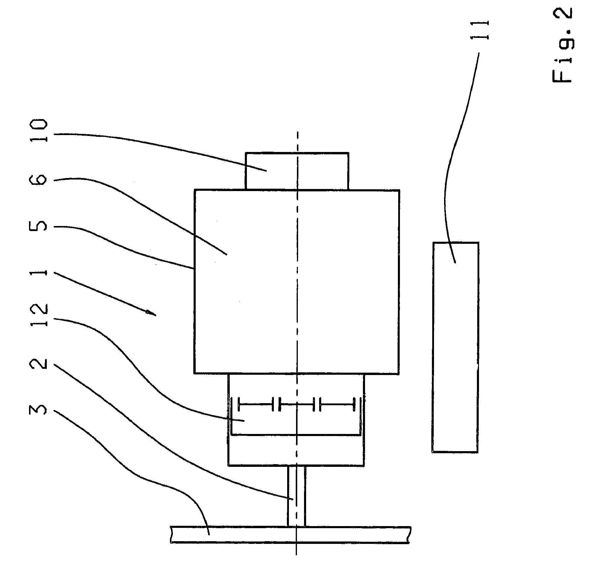
[0024]FIG. 1 is a first embodiment of a steering unit 1 as per the invention. It comprises a helm 3 fixed to a shaft 2 in a non-rotatable manner. In the illustrated embodiment, the shaft is connected to the helm via a screw nut 4.

[0025]As the device to produce a mechanical resistance to the steering movement, an electric motor 6 is arranged in a housing 5. The rotor 7 of the motor in the illustrated example is designed as a hollow shaft through which the shaft 2 passes, wherein the shaft 2 is fixed to the rotor 7 in a non-rotatable manner. The connection between rotor 7 and shaft 2 can be implemented, for example, by welding or by positive fit; it is also possible that the connection be made by means of a suitable profile, for example a spline profile. The housing 5 of the electric motor can be made of aluminum, steel, or cast iron.

[0026]As is evident in FIG. 1, the stator 8 of the electric motor 6 is fixed to the housing 5 in a non-rotatable manner. Furthermore, the shaft 2 is seat...


PUM


Abstract

A steering unit (1), for a steer-by-wire ship control system, comprises a steering wheel (3), a controller (11) that is connected to the electronic controller of the ship control system (ECU) via a CAN bus, a sensor (10) for detecting an angular position of the steering wheel (3), and a unit for generating mechanical resistance in the steering wheel (3), in which the unit for generating mechanical resistance in the steering wheel (3) is an electric motor (8) and the shaft (2) of the steering wheel (3), that is rotationally fixed to the steering wheel (3), is rotationally fixed to the rotor (7) of the electric motor (6), and the stator (8) of the electric motor (6) is rotationally fixed to the housing (5) of the electric motor (6).

Description

[0001]This application is a National Stage completion of PCT / EP2008 / 062897 filed Sep. 26, 2008, which claims priority from German patent application serial no. 10 2007 048 077.8 filed Oct. 15, 2007.FIELD OF THE INVENTION[0002]The present invention relates to a steering unit for a steer-by-wire ship control system. Furthermore, the invention relates to a method for operation of the steering unit.BACKGROUND OF THE INVENTION[0003]Steer-by-wire systems are known from the prior art which can also be used in ship control engineering. In systems of this type, the steering commands input via a steering unit are detected by a sensor and passed, via a control unit, to an actuator, which executes the steering command. In an advantageous manner, no mechanical connection exists between the helm (steering wheel) and the rudder and / or in the case of a motor vehicle, between the steering wheel and the steered wheels.[0004]In ship control engineering, the steering units connected to the helm are usu...

Claims


Application Information

Patent Timeline
Patent Type & Authority Patents(United States)
IPC IPC(8): B63H25/00
CPCB63H25/24B63H25/02
Inventor ZANFEI, ADRIANO
Owner ZF FRIEDRICHSHAFEN AG
Learn More