
Vibration-damped holder for additional handle

a vibration-damped and handle technology, applied in the field of vibration-damped holder for additional handle, can solve the problems of damping means tearing and handle means being destroyed, and achieve the effects of convenient detachment, high strength, and added stability

Active Publication Date: 2012-09-04
AEG ELECTRIC TOOLS
View PDF29 Cites 22 Cited by
  • Summary
  • Abstract
  • Description
  • Claims
  • Application Information

AI Technical Summary

Benefits of technology

"The present invention provides a damper for a power tool that can effectively dampen vibrations along an axis of vibration, particularly in the handle of the tool. The damper includes a distancing means that is dimensioned so that the ratio of the distance between the handle and the damping means is at least 2:1. The damping means is an elastic element that can show fatigue over time, so the invention also includes a stopper element to prevent damage to the damping means. The damper can be easily attached to different power tools and can be easily detached for transport or replacement. The handle of the power tool includes the damper and a handle means connected with the damper, which can effectively dampen vibrations and make the tool easier to use."

Problems solved by technology

Such elements are advantageous because the damping means may show symptoms of fatigue during its operation, which in an extreme case may lead to the destruction of the damping means and possibly the tearing-off of the handle means.

Method used


Image

  • Vibration-damped holder for additional handle
  • Vibration-damped holder for additional handle
  • Vibration-damped holder for additional handle

Examples


Embodiment Construction

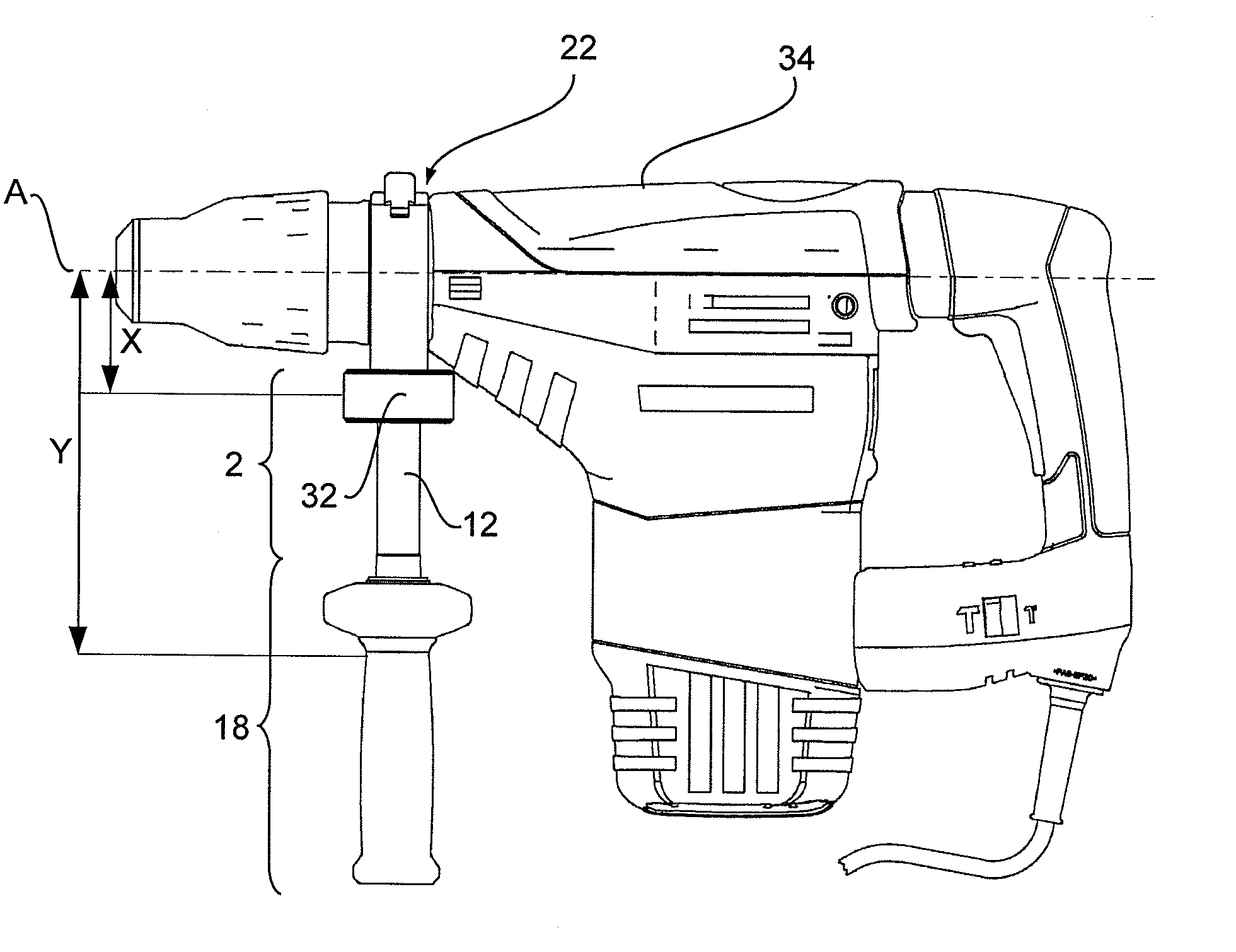
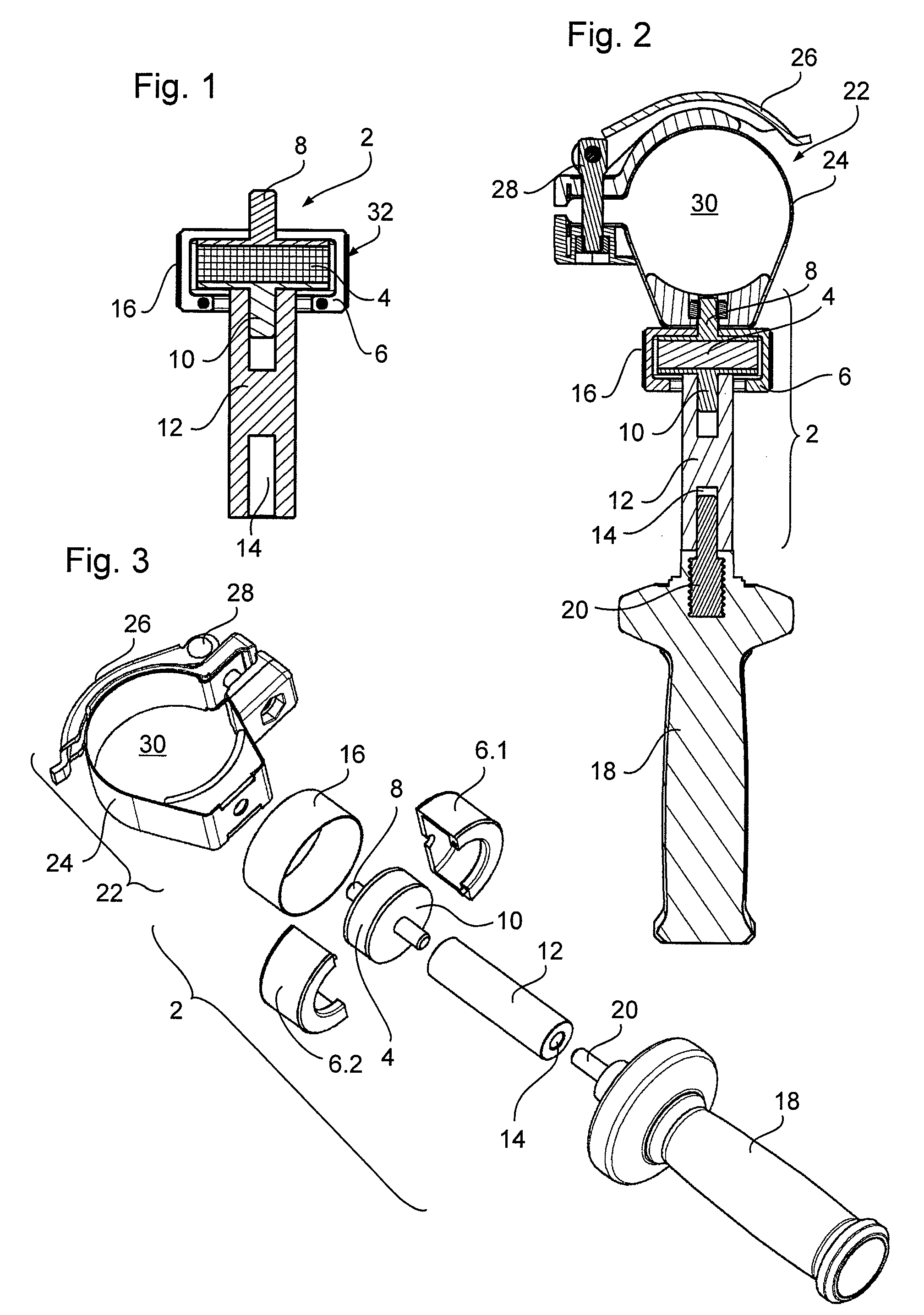
[0025]FIG. 1 shows a sectional view of a damper 2 having a damping means, such as a damping arrangement 32, and a distancing means, such as a spacer 12. The section through the damper 2, which has a generally cylindrical form, is substantially taken along the cylinder axis of the damper 2. In the upper part of the figure there is a damping means 32 which has an elastic element 4, a first connecting element 8 and a second connecting element 10 in a two-part cladding 6. The cladding forms a cylinder having a first diameter in which the elastic element 4 shown in FIG. 1 is also formed cylindrically and is inserted therein. In this exemplary embodiment, the elastic element 4 is formed of NBR (nitrile rubber), wherein the elastic element 4 may also be formed of other elastic materials, a coil spring or the like.

[0026]One of the connecting elements 8, 10 is respectively attached to the upper and lower front faces of the cylindrical elastic element 4. The first connecting element 8, which ...


PUM


Abstract

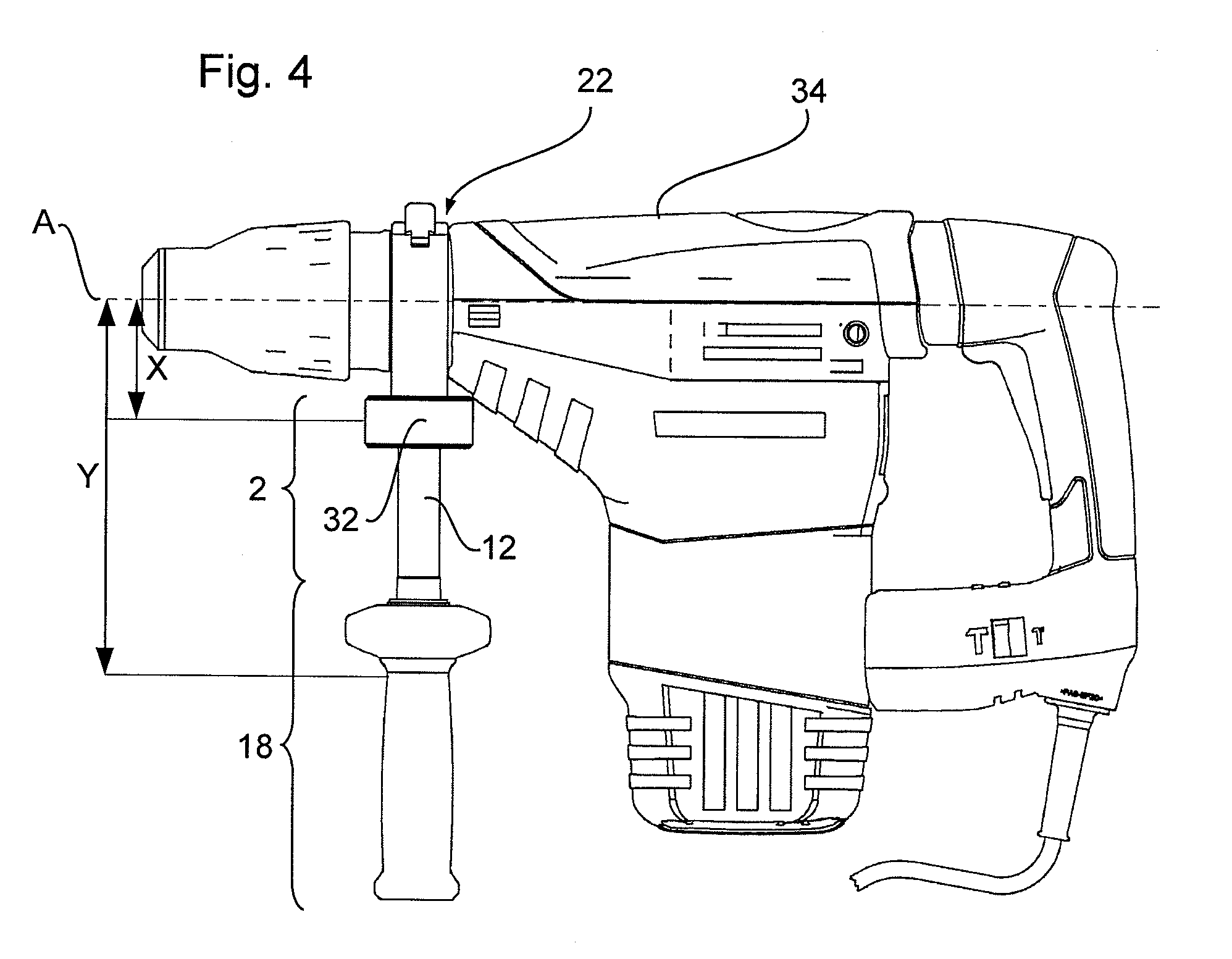
A damper for mounting between a power tool, having an axis of vibration, and a handle. The damper includes a damping arrangement for damping impacts and a spacer. The spacer is dimensioned so that, when the damper is mounted to the power tool, a ratio of a first distance between the axis of vibration and the handle to a second distance between the axis of vibration and the damping arrangement is at least 2:1. Further, a handle having such a damper for a power tool, as well as the corresponding power tool having such a handle, are described.

Description

REFERENCE TO RELATED APPLICATIONS[0001]This application is related to, and claims priority from, European Patent Application No. 08 009 186.1, filed May 19, 2008, entitled “VIBRATION-DAMPED HOLDER FOR ADDITIONAL HANDLE,” the entirety of which is incorporated by reference herein and made a part of the present specification.BACKGROUND OF THE INVENTION[0002]1. Field of the Invention[0003]The invention relates to a damper for mounting between a power tool having an axis of vibration, on the one hand, and a handle device for the power tool, on the other hand, wherein the damper comprises a damping means for damping impacts (absorbing shocks) and a distancing means. The invention further relates to a handle for a power tool having an axis of vibration and to a power tool having an axis of vibration, in particular a drill or impact drill or a hammer drill.[0004]2. Description of the Related Art[0005]Hand-operated machine tools such as power tools, for example angle grinders or power cutter...

Claims


Application Information

Patent Timeline
Patent Type & Authority Patents(United States)
IPC IPC(8): B25D17/24
CPCB25F5/006B25F5/026
Inventor OESTERLE, MARKUSROBIEU, THOMAS
Owner AEG ELECTRIC TOOLS
Learn More