Travelling toy system

a toy system and travel technology, applied in the field of traveling toy systems, can solve the problems of poor motion of image display, and difficult to make viewers of a traveling toy system, so as to reduce power consumption

Inactive Publication Date: 2012-09-04
KONAMI DIGITAL ENTERTAINMENT CO LTD
View PDF17 Cites 10 Cited by
  • Summary
  • Abstract
  • Description
  • Claims
  • Application Information

AI Technical Summary

Benefits of technology

[0005]It is an object of the present invention to provide a traveling toy system in which a smooth motion picture can be displayed so as not to make viewers feel something strange even when there is large variation in the traveling speed of the traveling toy on which the video camera is mounted, and electric power consumption in total can be reduced.
[0006]Another object of the present invention is to provide a traveling toy system in which the amount of information transmitted to a video display device can be reduced.
[0007]A further object of the present invention is to provide a traveling toy system in which data volume of a video signal transmitted to a video display device can be suppressed even when the frame rate of a video camera is changed.

Problems solved by technology

However, if the frame rate (the number of frames per second) of the video camera is determined based on the condition that the traveling speed of the traveling toy is low even though the variation in the traveling speed is large, when the traveling speed of the traveling toy is high, the motion of image display is not so smooth compared with when the traveling speed of the traveling toy is low.
In particular, since the objects to be captured by such toy are in many cases household utensils of daily use installed in the room and are not a vast and vague landscape as seen from a real vehicle, viewers are very likely to feel something strange.
Accordingly, it has been difficult for a traveling toy system to make viewers feel as if they were really riding on the traveling toy.
However, in this situation, motion pictures taken at a high frame rate must be always displayed even when the traveling speed of the traveling toy is low, which means a large amount of information is always transmitted to the video display device.
As a result, there is a problem with an increased total amount of power consumption.
To solve the problem, it is necessary to mount a large-capacity electric storage means for power supply onto the traveling system, which makes the toy more expensive.

Method used


Image

  • Travelling toy system
  • Travelling toy system
  • Travelling toy system

Examples


Embodiment Construction

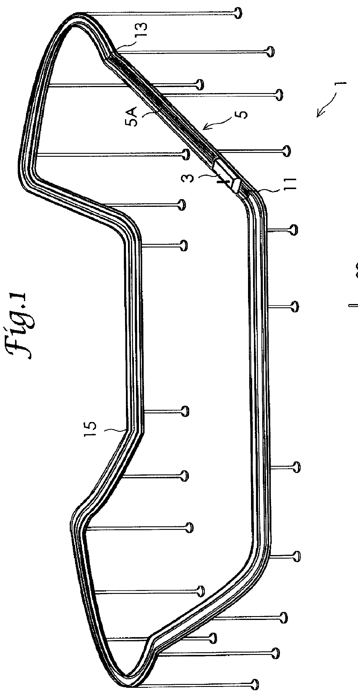
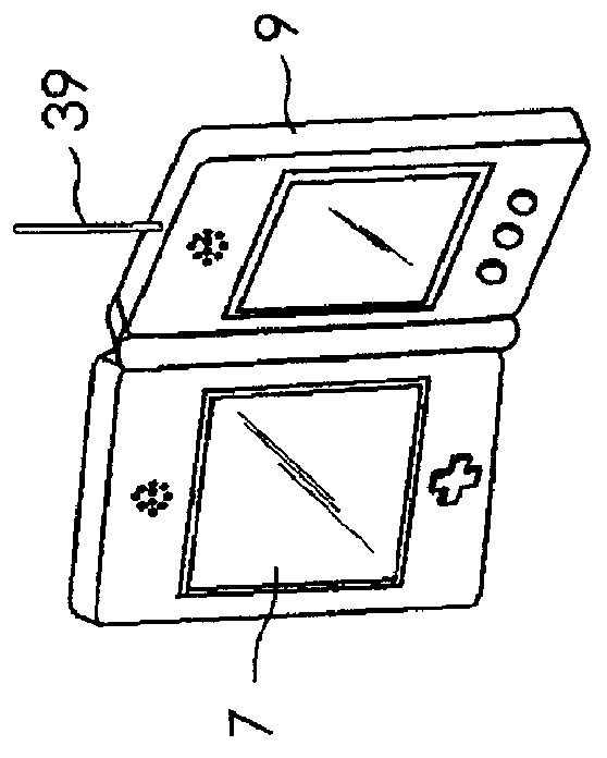
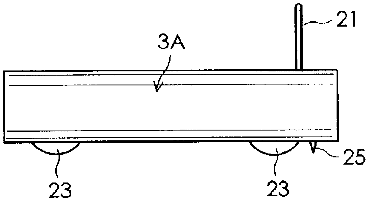
[0039]Preferred embodiments of the present invention will now be described hereinbelow with reference to the drawings FIG. 1 shows a traveling toy system according to one embodiment of the present invention. The traveling toy system 1 comprises a traveling toy 3, a traveling toy carrier device 5, a dedicated controller 9 equipped with a display screen 7, and a traveling lane 15. In this embodiment, the traveling toy carrier device 5 is arranged separately from the traveling toy 3 so as to constitute a part of the traveling lane 15. The traveling toy carrier device 5 includes an entrance portion 11 through which the traveling toy 3 enters and an exit portion 13 through which the traveling toy 3 returns the traveling lane. In FIG. 1, only a carrier portion 5A of the traveling toy carrier device 5 is shown and a driving portion for applying a driving force to the carrier portion 5A is not illustrated. The traveling toy carrier device 5 carries the traveling toy 3 from the entrance port...


PUM


Abstract

A traveling toy system is provided, in which it becomes possible to reduce the amount of information transmitted to a video display device. In the traveling toy system, a video camera, a video camera controller which is adjustably controls at least a frame rate of the video camera, a signal transmission device which transmits a video signal outputted from the video camera to a video display device, and electric storage means for power supply are mounted on the traveling toy which travels on a traveling lane using a potential energy. The traveling toy system further includes a traveling toy carrier device which carries the traveling toy from a position where the potential energy is low to a position where the potential energy is high. The video camera controller changes the frame rate so that when a traveling speed of the traveling toy is higher than a given speed, the frame rate may be increased from the frame rate at the time that the traveling speed is lower than the given speed.

Description

BACKGROUND OF THE INVENTION[0001]The present invention relates to a traveling toy system which displays images captured with a video camera, which is installed in a traveling toy that travels using a potential energy, on a video display device.[0002]Japanese Patent Application Publication No. 2006-279648 (JP2006-279648A) discloses a toy system in which a video camera, which is installed in a traveling toy operated by remote control, captures an image and transmits it to a video display device via the Internet so that the operator of the system can view the image captured by the video camera.[0003]In conventional traveling toy systems, images displayed on the video display device are captured at a fixed frame rate irrespective of the traveling speed of the traveling toy. When the traveling speed of the traveling toy does not vary so much, the image quality displayed on the video display device is almost stable even if the traveling speed of the traveling toy is changed. Accordingly, ...

Claims


Application Information

Patent Timeline
Patent Type & Authority Patents(United States)
IPC IPC(8): A63F13/00A63J5/02H04N7/18A63F13/213A63F13/235A63H17/00A63H17/26A63H18/02A63H18/06A63H18/12A63H33/22A63H33/26
CPCA63H18/02A63F2300/1093A63F2300/204A63F2300/69A63H17/32A63H18/04
Inventor ANDO, MAKOTONAKANO, MAKOTO
Owner KONAMI DIGITAL ENTERTAINMENT CO LTD
Why Eureka
Try Eureka