Magnetic memory with a magnetic tunnel junction written in a thermally assisted manner, and method for writing the same

a magnetic tunnel junction and memory technology, applied in the field of magnetic memories, can solve the problems of limited capacity, addressing errors in writing, and limiting the possibility of integration, and achieve the effect of low power consumption and thermal and temporal stability

Active Publication Date: 2006-12-28
CENT NAT DE LA RECHERCHE SCI +1
View PDF19 Cites 52 Cited by
  • Summary
  • Abstract
  • Description
  • Claims
  • Application Information

AI Technical Summary

Benefits of technology

[0037] The object of the present invention is to further optimize the advantages mentioned above by lowering the magnetization reversal field of the memory point by selecting a particular geometry of said memory point, and in particular by implementing a circular geometry. It has in fact been demonstrated—and this is the heart of the present invention—that in the context of such a circular geometry of the memory point, the anisotropy of the form of the memory point which is responsible for an increase in the magnetization reversal field is zero. As a consequence, the electric power required to effect the writing of a memory point may be lowered considerably in the thermally assisted writing approach. This result is a decisive advantage, in particular for portable applications and applications in SOI technology (silicon on insulator).

Problems solved by technology

By virtue of its architecture, this technology allows non-volatile memories to be made with a simple technology, but having limited capacity.
The fact that the memory elements are connected in series along each line limits the possibility of integration since the signal grows increasingly weak when the number of elements increases.
If the distribution function of the reversal fields for all the memory points is wide (it is not uniform owing to manufacturing constraints and intrinsic statistical fluctuations), it is necessary that the magnetic field at the selected memory point be greater than the highest reversal field of distribution, at the risk of accidentally reversing certain memory points situated on the corresponding line or column, the reversal field of which, located in the lower part of distribution, is weaker than the magnetic field generated by the line or the column alone.
In other words, this selection architecture by a magnetic field using lines and columns or conductors can easily lead to addressing errors when writing.
With this approach, however, the temporal or thermal stability of the system is no longer guaranteed because it is the same physical parameter that governs the writing process and thermal stability: if magnetocrystalline anisotropy is high, the system is stable (in time and in temperature) and both states of the memory point are well defined.
On the other hand, the magnetic field required to reverse the magnetization of said memory point from one stable state to another (the writing field) is significant, and therefore the power consumed during the writing process is great.
Conversely, if magnetocrystalline anisotropy is low, the power consumed when writing is low, but thermal and temporal stability is no longer assured.
Furthermore the two rest states of the memory point are ill-defined because the magnetic structures within the memory point are complex and multiple depending on the cycle in the field.
In other words, it is impossible to simultaneously ensure low power consumption and thermal and temporal stability.

Method used


Image

  • Magnetic memory with a magnetic tunnel junction written in a thermally assisted manner, and method for writing the same
  • Magnetic memory with a magnetic tunnel junction written in a thermally assisted manner, and method for writing the same
  • Magnetic memory with a magnetic tunnel junction written in a thermally assisted manner, and method for writing the same

Examples


Embodiment Construction

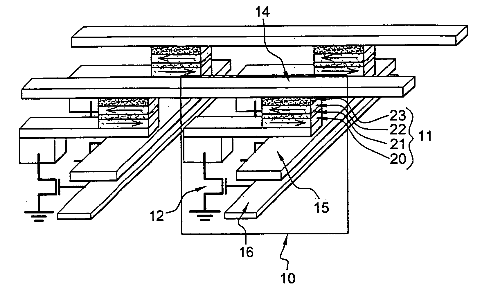
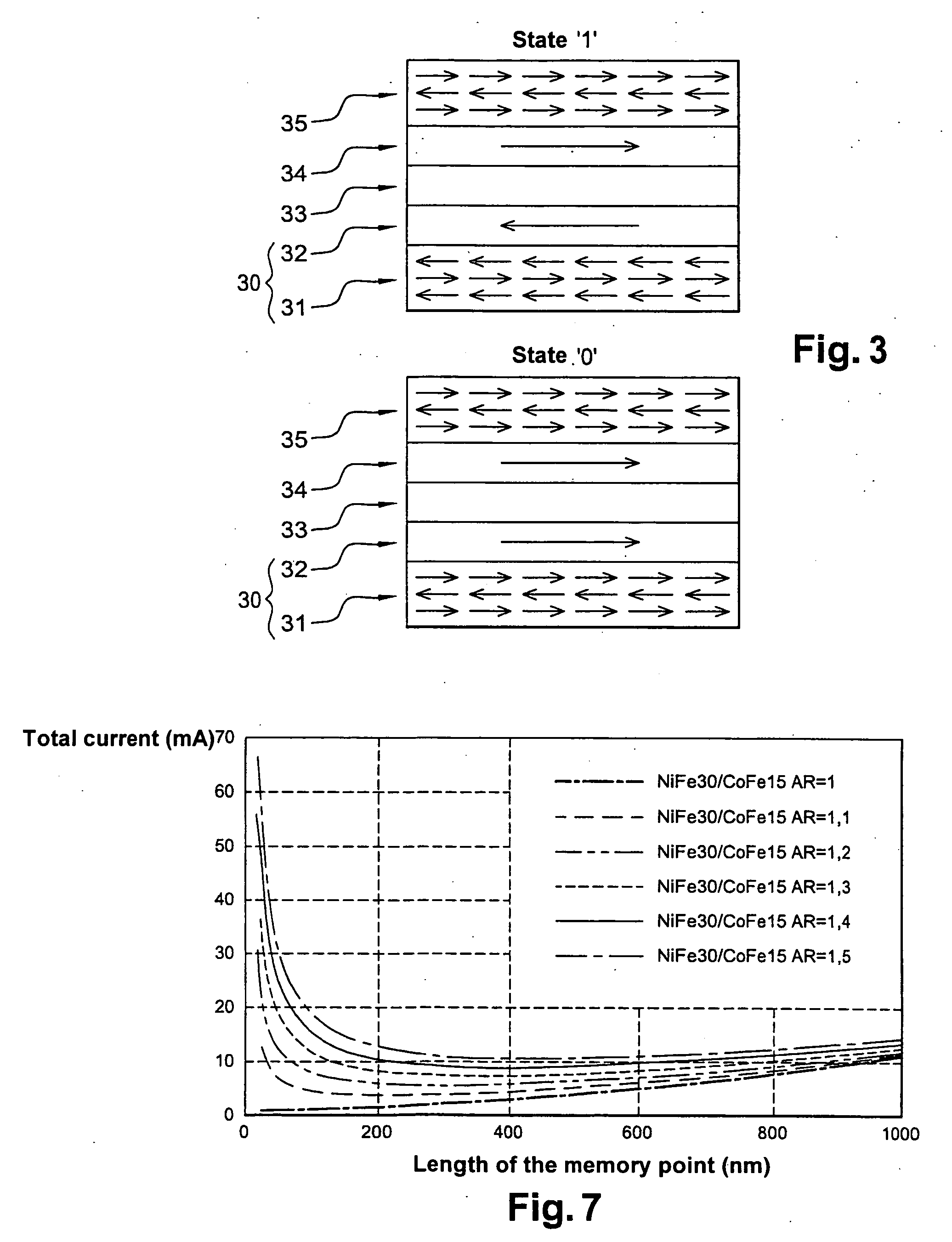
[0056]FIG. 3 shows the magnetization orientations of the different layers that form a memory point, in particular in the prior art. According to the latter, the storage layer (30) consists of a stack comprising at least one ferromagnetic layer (32) and an anti-ferromagnetic layer (31). These two layers are deposited in such a manner that a magnetic exchange coupling is established between the two layers. The stack of the complete memory point also comprises at least one insulating layer (33) and a reference layer (34), advantageously combined with a trapping layer (35). This architecture is described by the term trapped storage layer. Multiple advantages are afforded by this architecture: [0057] the stability limit of the memory points is extended; [0058] insensitivity to external magnetic fields; [0059] possibility of effecting multi-level storages.

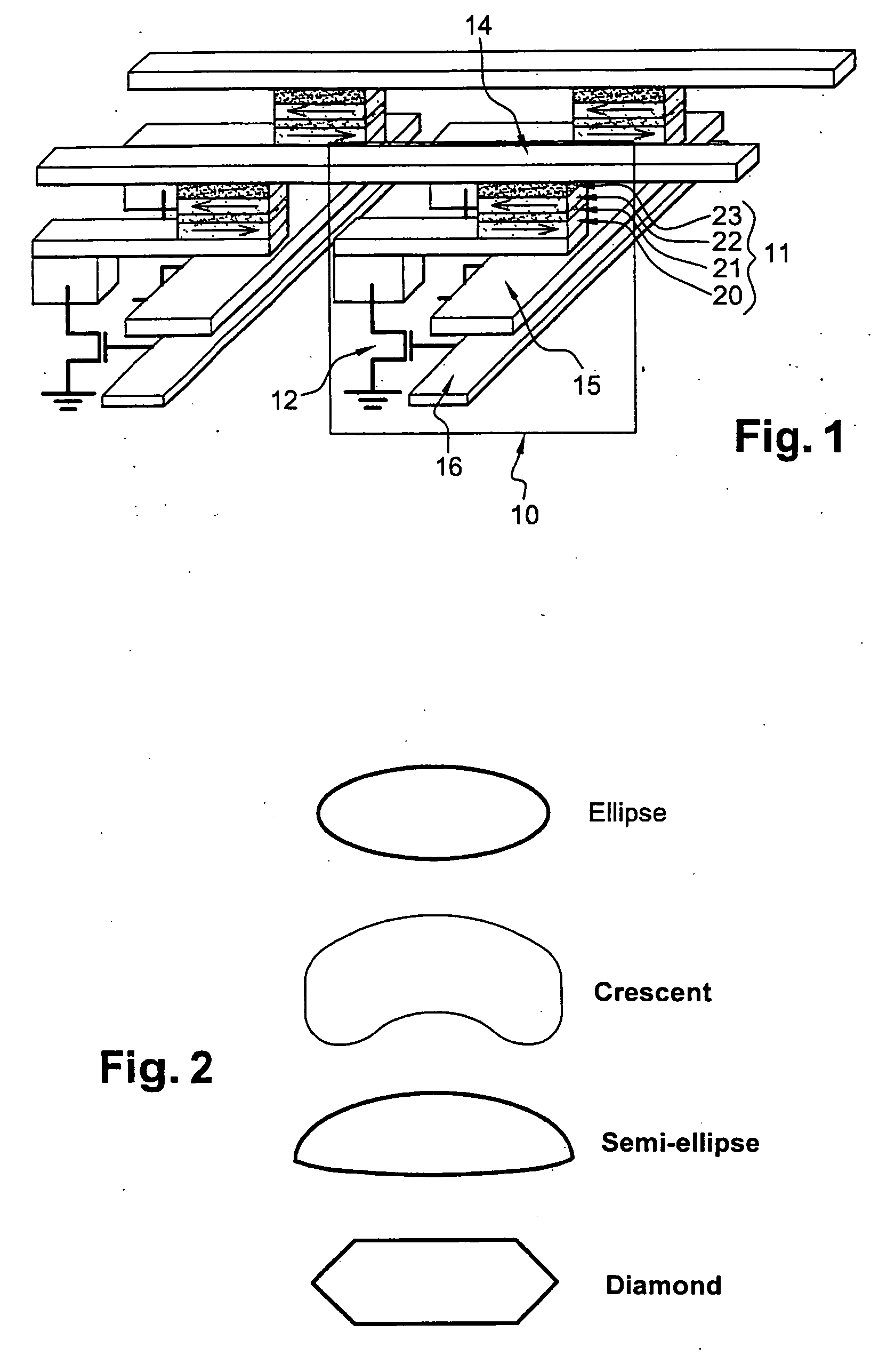
[0060] According to the invention, the memory point utilizing a trapped storage layer no longer has an elongated but a circular form a...


PUM


Abstract

The invention relates to a magnetic memory written in a thermally assisted manner, each memory point (40) consisting of a magnetic tunnel junction, and the cross-section of the memory parallel to the plane of the layers forming the tunnel junction being circular or essentially circular. Said tunnel junction comprises at least one trapped layer (44) with a fixed magnetisation direction, a free layer (42) with a variable magnetisation direction, and an insulating layer (43) arranged between the free layer (42) and the trapped layer (44). According to the invention, the free layer (42) is formed from at least one soft magnetic layer and a trapped layer (41), said two layers being magnetically coupled by contact, and the operating temperature of the reading memory or resting memory is selected in such a way that it is lower than the blocking temperature of the respectively free and trapped layers.

Description

TECHNICAL FIELD [0001] The present invention relates to the field of magnetic memories, and in particular to non-volatile random access magnetic memories that allow data to be stored and read in electronic systems. More specifically, it concerns random access magnetic memories, known as M-RAM, comprised of a magnetic tunnel junction. [0002] The invention also concerns a thermomagnetic method for writing in such a memory. PRIOR ART [0003] M-RAM magnetic memories have aroused renewed interest with the development of magnetic tunnel junctions (MTJ) having a high magnetoresistance at ambient temperature. These random-access magnetic memories offer numerous advantages: [0004] speed (writing and reading take only a few nanoseconds); [0005] non-volatility; [0006] lack of fatigue during reading and writing; [0007] insensitivity to ionizing radiation. [0008] As such, they are likely to replace memories using more conventional technology, based on the charge state of a capacity (DRAM, SRAM, F...

Claims


Application Information

Patent Timeline
Patent Type & Authority Applications(United States)
IPC IPC(8): G11C11/14G11C11/16
CPCG11C11/5607G11C11/16G11C11/1675G11C11/161H10B61/00H10N50/80
Inventor NOZIERES, JEAN-PIERREDIENY, BERNARDREDON, OLIVIERSOUSA, RICARDOPREJBEANU, IOAN-LUCIAN
Owner CENT NAT DE LA RECHERCHE SCI
Why Eureka
Try Eureka