Electronic device cooling apparatus and electronic device including the same

a technology of electronic devices and cooling apparatuses, which is applied in the direction of lighting and heating apparatus, semiconductor devices, solid-state devices, etc., can solve the problems of deterioration in reliability of piping, affecting the efficiency of cooling apparatus, and affecting the reliability of cooling apparatus, etc., to achieve the effect of low cost of cooling apparatus

Active Publication Date: 2012-09-11
MAXELL HLDG LTD
View PDF13 Cites 12 Cited by
  • Summary
  • Abstract
  • Description
  • Claims
  • Application Information

AI Technical Summary

Benefits of technology

[0009]The cooling apparatus 10′ shown in FIG. 6 has a configuration in which the outflow port of the radiator (refrigerant cooling portion) 14′ is connected to the sucking port of the pump 12′ through the piping member. Accordingly, in a configuration in which, for example, the pump 12′ and the radiator 14′ are separately arranged on the both sides of the heat generating portion cooling unit 11′, the length between the pump 12′ and the radiator 14′ becomes long. Therefore, the piping member is also arranged across the long length, and a space for placing the piping member is needed. In addition, when the apparatus is incorporated or used, the piping member, the sucking port of the pump 12′, and the outflow port for refrigerant liquid of the radiator 14′ are easily damaged by the arrangement structure due to the effects of external force or contact with other portions, and thus there is a possibility of deterioration in reliability of the piping. Further, the arrangement structure hampers further downsizing and low cost of the cooling apparatus 10′.
[0011]In view of the foregoing circumstances of the conventional techniques, an object of the present invention is to simplify piping, to improve the reliability, and to realize downsizing and low cost of an electronic device cooling apparatus which allows refrigerant liquid to circulate and flow in a cooling system by using a pump so as to cool a heat generating portion of an electronic device.
[0012]The present invention provides a practical electronic device cooling apparatus with high cooling-performance.

Problems solved by technology

In addition, when the apparatus is incorporated or used, the piping member, the sucking port of the pump 12′, and the outflow port for refrigerant liquid of the radiator 14′ are easily damaged by the arrangement structure due to the effects of external force or contact with other portions, and thus there is a possibility of deterioration in reliability of the piping.
Further, the arrangement structure hampers further downsizing and low cost of the cooling apparatus 10′.
Further, in the technique described in JP-A-2007-142068, since the pump is integrally configured with the fin portion in the casing, the structure becomes complicated.
In addition, it is difficult to use a general-purpose pump due to restriction of the structure and dimension of the pump by the fin portion, and there is a possibility of increasing the cost.
In addition, since the structure formed by integrally coupling the pump to the fin portion in the casing is attached to the heat generating portion, there is a possibility that oscillation of the pump is easily conducted to the heat generating portion and the circuit substrate, the heat generating portion and the circuit substrate are damaged and oscillation and noise of the electronic device are increased.
It is impossible to exchange one of the pump and the fin portion.
It is difficult to adapt the technique to a cooling apparatus in which three elements are piled up in the order of the pump, the radiator, and the reserve tank, or a cooling apparatus in which three elements are not formed as one block.

Method used


Image

  • Electronic device cooling apparatus and electronic device including the same
  • Electronic device cooling apparatus and electronic device including the same
  • Electronic device cooling apparatus and electronic device including the same

Examples


Embodiment Construction

[0020]Hereinafter, an embodiment of the present invention will be described using the drawings.

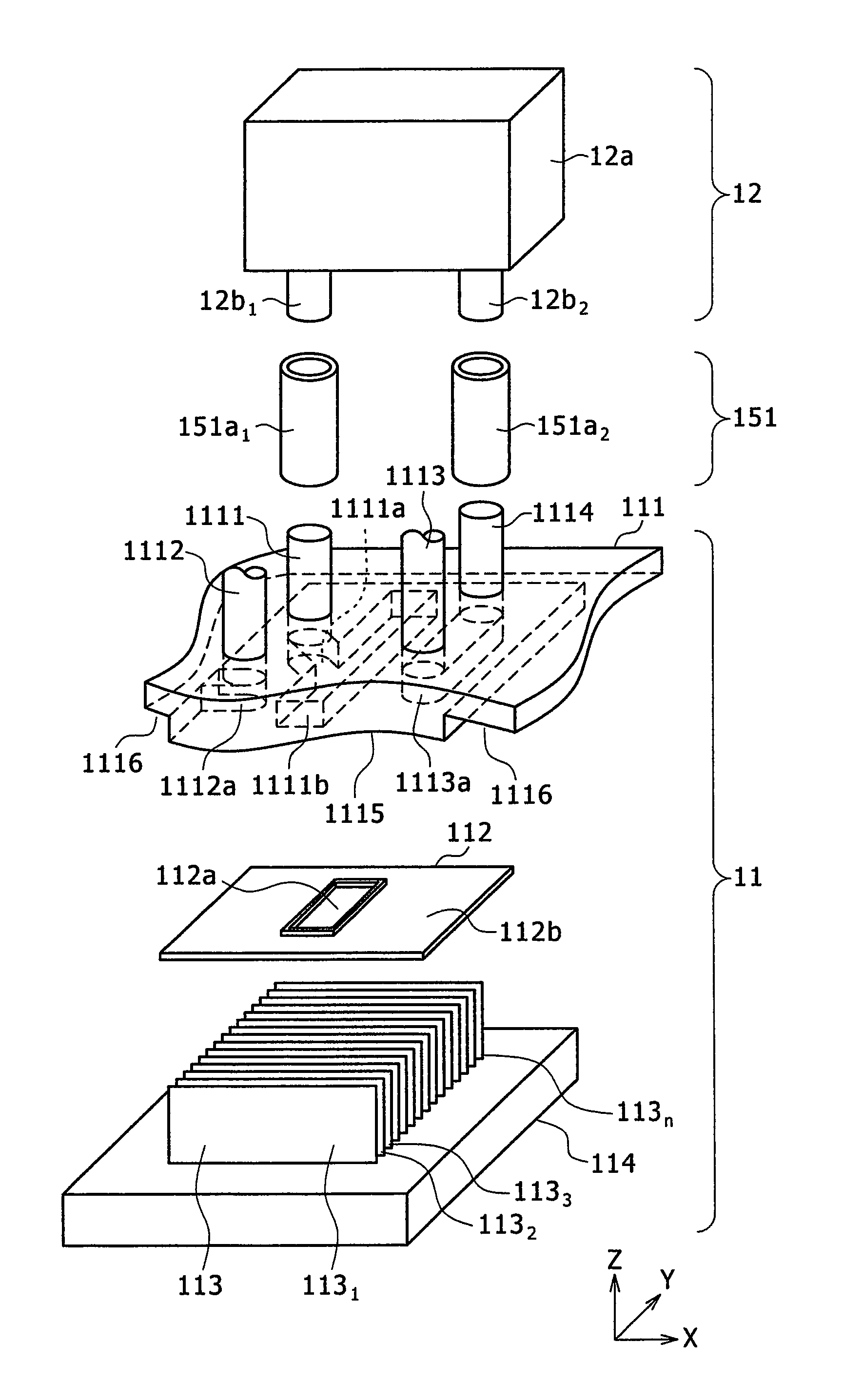
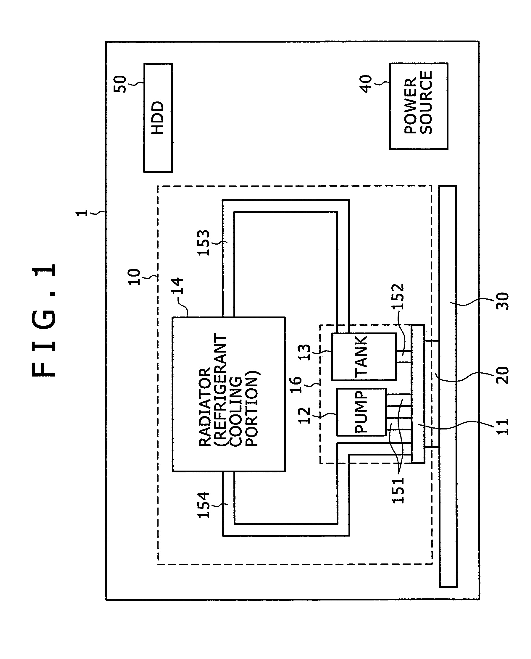
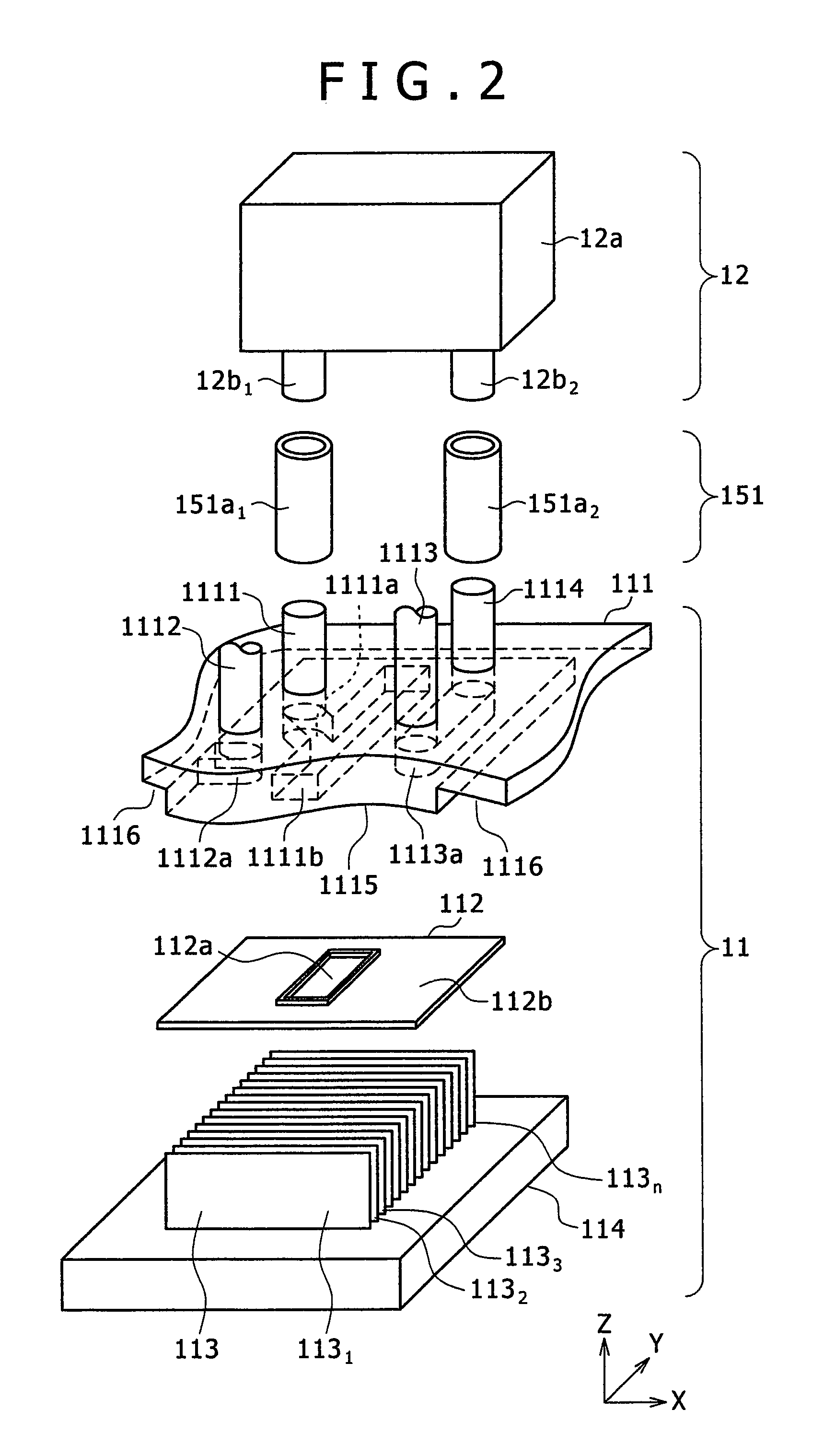
[0021]FIGS. 1 to 5 are explanatory views of an electronic device cooling apparatus as an embodiment of the present invention. FIG. 1 is a block diagram showing the entire configuration of the electronic device cooling apparatus according to the embodiment of the present invention, FIG. 2 is a view showing an internal configuration of a heat generating portion cooling unit and a connecting state between the heat generating portion cooling unit and a pump in the electronic device cooling apparatus of FIG. 1, FIG. 3 is a cross sectional view of a configuration of the heat generating portion cooling unit in the electronic device cooling apparatus of FIG. 1, FIG. 4 is a perspective view showing a configuration on the inner surface side of a case member used for the heat generating portion cooling unit in the electronic device cooling apparatus of FIG. 1, and FIG. 5 is a plan view showing a conf...


PUM


Abstract

As an electronic device cooling apparatus which allows refrigerant liquid to circulate and flow in a cooling system by using a pump so as to cool a heat generating portion of an electronic device, a heat generating portion cooling unit which is connected to the pump, which receives heat from the heat generating portion of the electronic device, and which releases the heat to the refrigerant liquid through a fin portion so as to cool the heat generating portion includes independently therein a first flow channel through which the refrigerant liquid discharged from a discharging port of the pump is drawn in to be guided to the outside of the heat generating portion cooling unit through the fin portion, and a second flow channel through which the refrigerant liquid cooled at the outside is drawn in to be guided towards a sucking port of the pump.

Description

CLAIM OF PRIORITY[0001]The present application claims priority from Japanese patent application serial No. P2008-114025, filed on Apr. 24, 2008, the content of which is hereby incorporated by reference into this application.BACKGROUND OF THE INVENTION[0002]1. Technical Field of the Invention[0003]The present invention relates to a cooling apparatus of an electronic device such as a personal computer, and particularly to a configuration of a cooling apparatus of a type which allows refrigerant liquid to circulate in a cooling system by using a pump.[0004]2. Description of the Related Art[0005]In recent years, high-performance semiconductor integrated circuits such as CPUs of personal computers are mounted in electronic devices. High speed and high integration of the semiconductor integrated circuits has been rapidly advanced along with demands for high-performance electronic devices, and the heating value thereof has increased as compared to that of the conventional circuits. When th...

Claims


Application Information

Patent Timeline
Patent Type & Authority Patents(United States)
IPC IPC(8): F28F7/00
CPCH05K7/20272H01L2924/0002H01L2924/00
Inventor OIKAWA, HIRONORI
Owner MAXELL HLDG LTD
Why Eureka
Try Eureka