Prop head for ceiling formwork

Active Publication Date: 2012-09-11
PERI GMBH
View PDF39 Cites 24 Cited by
  • Summary
  • Abstract
  • Description
  • Claims
  • Application Information

AI Technical Summary

Benefits of technology

[0017]If the skid is distant in an asymmetrical manner from the longitudinal axis of the end piece facing the concrete ceiling, the space required by the prop head in accordance with the invention can be reduced while the maximum hinge angle remains the same. The more distant part of the skid is then locked in the profile element in a maximum hinged position. Such saving in space helps further improve the accessibility of the room below the ceiling formwork.
[0018]In a preferred embodiment, the fastening means comprise screws, wherein the screws can be used to shape the profile element in such a way that the skid is clamped in the profile element. Clamping by means of screws enables simple and very stable fixation of the skid in the profile element in the hinged posit

Problems solved by technology

The girders of the concrete formwork can only absorb the vertical forces caused by the loads they support, since they can divert forces substantially only in their axial direction.
Furthermore, the bracing system considerably affects the accessibility of the room

Method used


Image

  • Prop head for ceiling formwork
  • Prop head for ceiling formwork
  • Prop head for ceiling formwork

Examples


Embodiment Construction

[0031]The figures of the drawings show a strongly schematic representation of the object in accordance with the invention and must not be understood as being true to scale. The individual components of the object in accordance with the invention are shown in a manner which allows good representation of their structure.

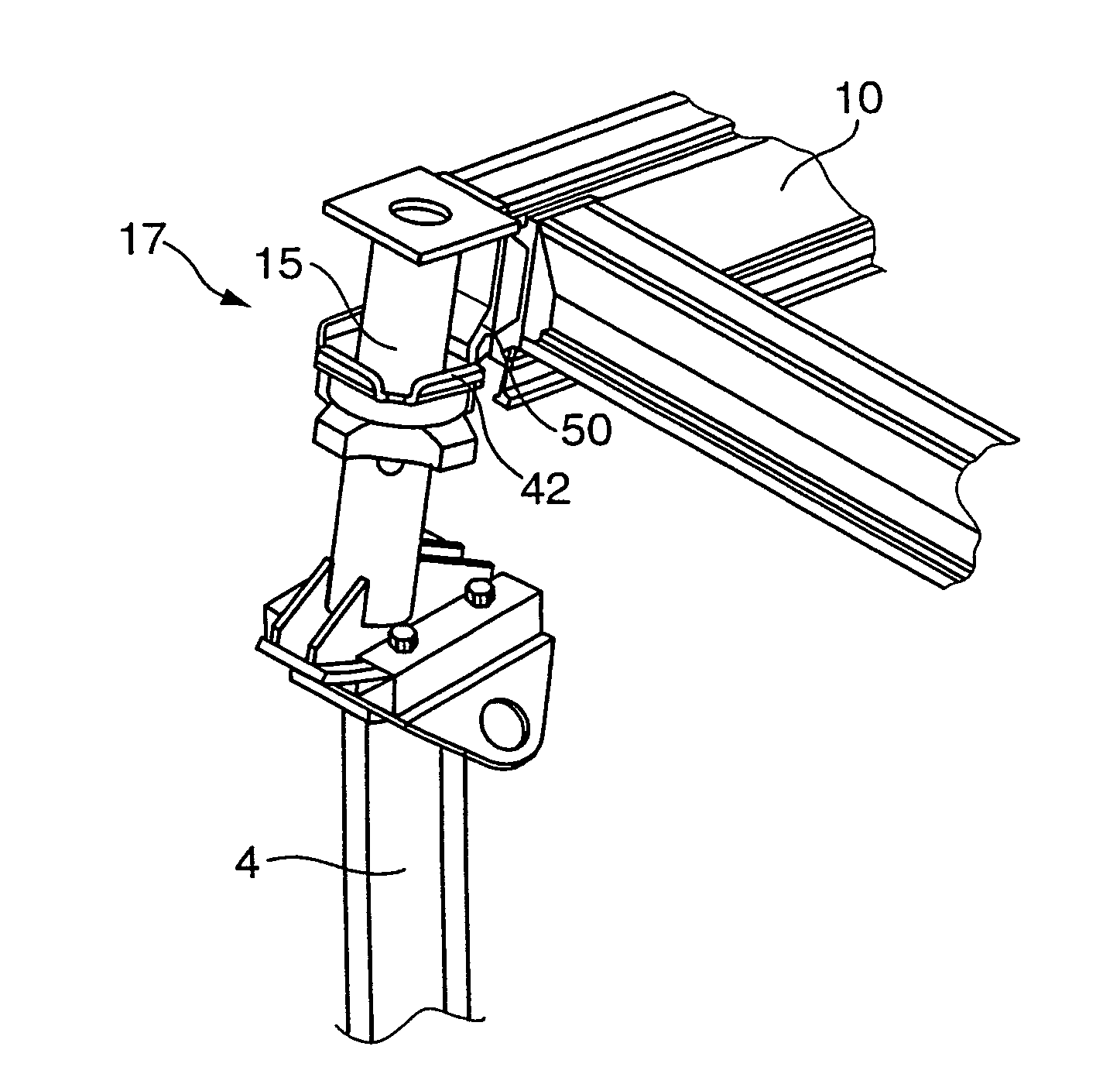
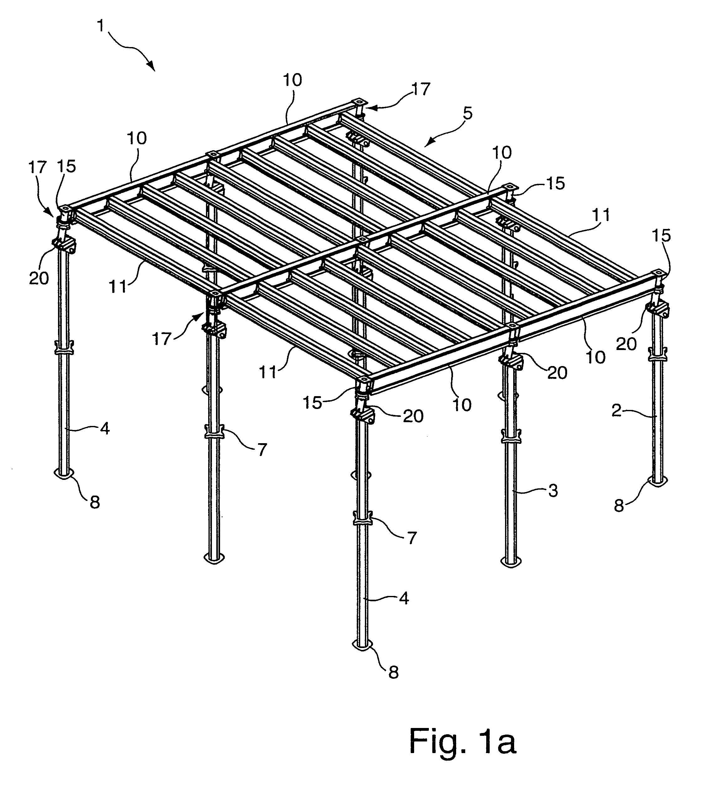
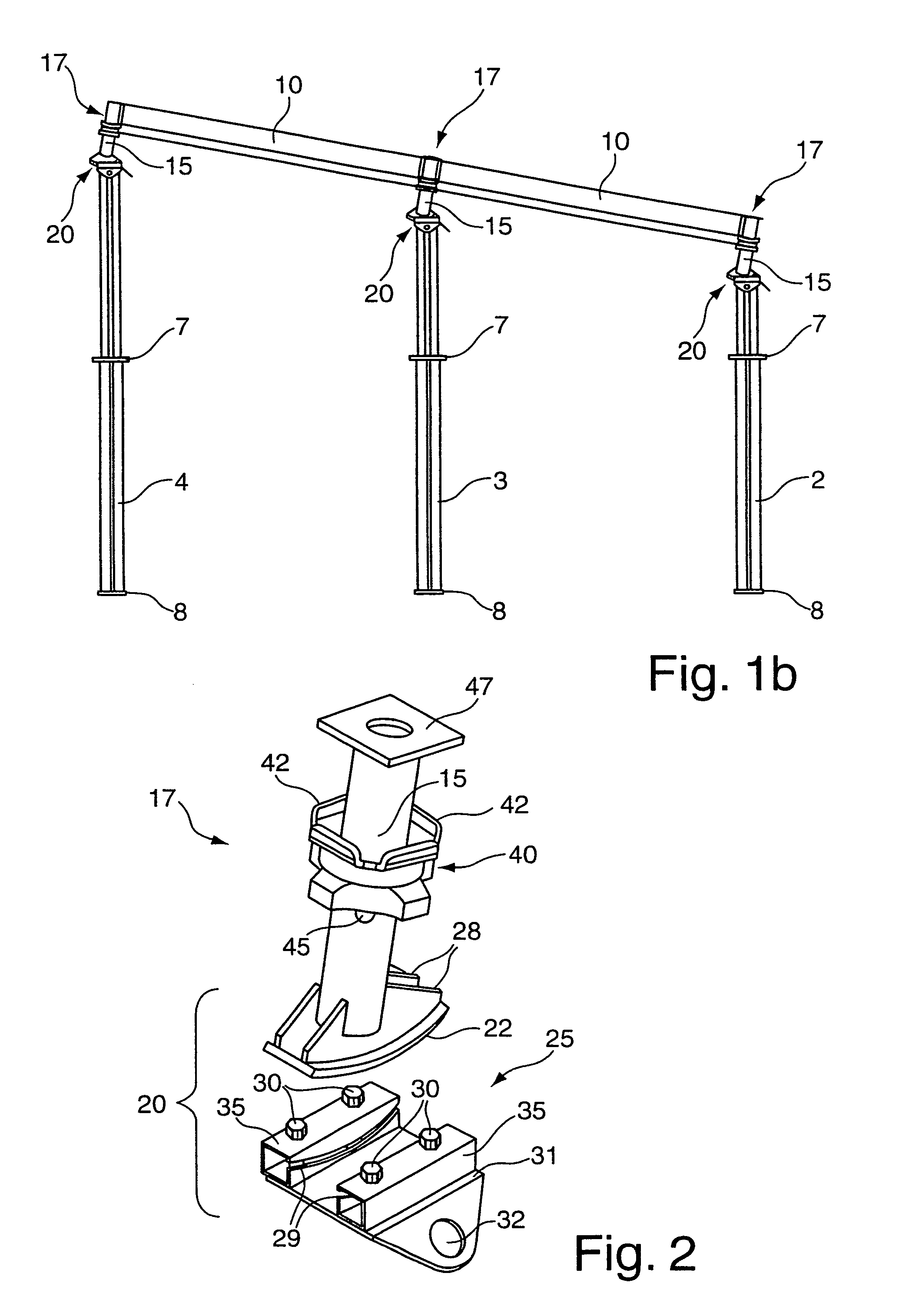
[0032]FIG. 1a shows a perspective view of formwork for a slanted concrete ceiling 1 in accordance with the invention, wherein the formwork for a concrete ceiling 1 has a grid formwork system 5 which rests on nine props 2,3,4. The formwork panels to be placed on the grid formwork system 5 to shape the surface of the ceiling to be concrete-cast are not shown in the figure. The ceiling to be concrete-cast is slanted at the back right in the embodiment shown in this figure. The props 2 located at the back in this figure are therefore shorter than the props 4 located at the front in this figure. FIG. 1b shows a side view of formwork for a concrete ceiling 1 as shown in FIG....


PUM


Abstract

A prop head (17) of a formwork prop for a concrete ceiling has an end piece (15) facing the concrete ceiling, the end piece (15) having a longitudinal axis which extends substantially perpendicular to the plane of the concrete formwork. The prop head (17) also has a hinge mechanism (20) at the end piece (15) end facing away from the concrete ceiling. The longitudinal axis of the end piece (15) can be placed in swiveled positions relative to the longitudinal axis of the prop in hinged positions of the hinge mechanism (20), the hinged positions being lockable by means of fastening means (30), preferably on the hinge mechanism (20). A load-introducing center of gravity formed by the end piece (15) end facing the concrete ceiling essentially lies on a line encompassing the longitudinal axis (62) of the prop (2, 3, 4) in the hinged positions.

Description

[0001]This application is the national stage of PCT / DE2007 / 002066 filed on Nov. 15, 2007 and also claims Paris Convention priority to DE 10 2006 055 306.3 filed on Nov. 23, 2006.BACKGROUND OF THE INVENTION[0002]The invention concerns a head for a prop of formwork for a concrete ceiling, having an end piece facing the concrete ceiling and of which the longitudinal axis extends perpendicular to the plane of the concrete formwork, and a prop of a concrete formwork, and a concrete formwork with such a prop head. The prop head in accordance with the invention is in particular suitable for use in formwork for slanted concrete ceilings, i.e. for concrete ceilings which have a vertical component of direction.[0003]Formwork for concrete-cast ceilings (ceiling formwork) usually comprises a system of steel or wood girders, for example, onto which the formwork panels which shape the bottom side of the concrete ceiling are placed. This is referred to as grid formwork. Alternatively, the formwork...

Claims


Application Information

Patent Timeline
IPC IPC(8): E04G17/00E04G25/00E04G11/38
CPCE04G11/483E04G11/486E04G2025/006
Inventor SCHWOERER, ARTUR
Owner PERI GMBH
Why Eureka
Try Eureka