Head attachment member, liquid ejection device, and head attachment method

a liquid ejection device and head attachment technology, applied in typewriters, printing, power drive mechanisms, etc., can solve the problems of difficult high-precision positioning, difficult high-precision relative angles of the four flat parts, and inconvenient use, so as to achieve high-precision alignment, enhance printing quality, and reduce errors

Active Publication Date: 2012-09-11
SEIKO EPSON CORP
View PDF5 Cites 21 Cited by
  • Summary
  • Abstract
  • Description
  • Claims
  • Application Information

AI Technical Summary

Benefits of technology

[0013]In view of the foregoing, an object of the present invention is to provide a head attachment member, a liquid ejection device, and a head attachment method whereby a liquid ejection head can easily be positioned in a predetermined position with high precision.
[0017]In this case, since positioning of the head attachment member with respect to the support drum in the manner described above is performed in a state in which alignment of the liquid ejection heads with respect to the head attachment unit is completed, the positioning of the liquid ejection heads and the support drum, particularly, the distances between the distal end surfaces of the liquid ejection heads and the peripheral surface of the support drum, can be made uniform without separately positioning each liquid ejection head with respect to the support drum, and the liquid ejection heads can be reliably fixed in predetermined positions with respect to the support drum in this state. This configuration can therefore contribute to enhanced printing quality.
[0022]According to this aspect, since alignment of the liquid ejection heads with respect to the head attachment member is performed in a state in which the head attachment member is kept horizontal, the imaging unit of the alignment device need only move in the horizontal plane, and movement in the vertical direction is not included. Error can therefore be reduced by a corresponding degree, and highly precise alignment is possible. In this state, the angle formed by the plate-shaped members is adjusted to a predetermined value by rotating the plate-shaped members via the hinge part, and the head attachment member is fixed in this state so as to maintain a predetermined positional relationship with respect to the support drum. The positioning of the liquid ejection heads and the support drum, particularly, the distances between the distal end surfaces of the liquid ejection heads and the peripheral surface of the support drum, can therefore be made uniform without separately positioning each liquid ejection head with respect to the support drum. This configuration can therefore contribute to enhanced printing quality.

Problems solved by technology

However, in a case in which a plurality of liquid ejection heads is radially arranged in the peripheral direction of a support drum, as in Japanese Laid-Open Patent Publication No. 2005-53227, since a printing bar in which a plurality of liquid ejection heads is attached as in Japanese Laid-Open Patent Publication No. 2005-53227 must be attached to the printing bar frame structure at different angles with respect to the support drum, each printing bar must be positioned with respect to the drum, which involves a complex operation, and problems arise in that highly precise positioning is difficult to achieve, and the attachment direction and the distances to the drum are no longer uniform.
The technique of Japanese Laid-Open Patent Publication No. 2000-289279 also has drawbacks in that the relative angles of the four flat parts are difficult to form with high precision with respect to the drum, positioning the liquid ejection heads in each of the four flat parts for attachment with respect to the drum is a complex operation, highly precise positioning is difficult to achieve, and the attachment direction and the distances to the drum are no longer uniform.
On the other hand, in the case of a liquid ejection device in which the ejection-receiving medium is wound onto the periphery of a drum which rotates about a shaft, and printing is applied to the ejection-receiving medium by inkjet recording heads provided on the periphery of the drum, surfaces parallel to the directions of lines tangent to various points on the drum must necessarily be a plurality of inclined surfaces, but it is difficult to increase precision of the positioning of the liquid ejection heads on inclined surfaces in predetermined positions.
Furthermore, it is complicated to manufacture a different head attachment member for each liquid ejection device provided with a rotating drum of a different diameter.
Incidentally, in the case of aligning the liquid ejection heads in the head attachment member in which the attachment surfaces are inclined, the need arises for the imaging unit of the alignment device to move not only in the horizontal direction but in the vertical direction as well, which introduces a corresponding amount of movement error, and not only is an increase in the precision of alignment inhibited, but in the case of fabricating a glass mask having an inclined shape, the glass mask is also difficult to fabricate.

Method used


Image

  • Head attachment member, liquid ejection device, and head attachment method
  • Head attachment member, liquid ejection device, and head attachment method
  • Head attachment member, liquid ejection device, and head attachment method

Examples


Embodiment Construction

[0032]The present invention will be described in detail based on embodiments.

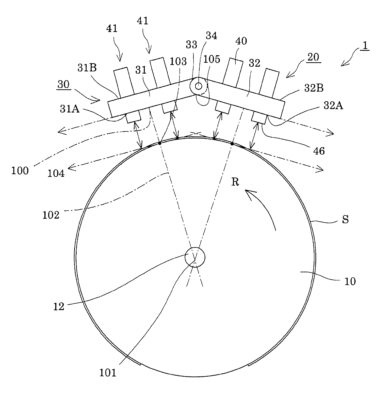
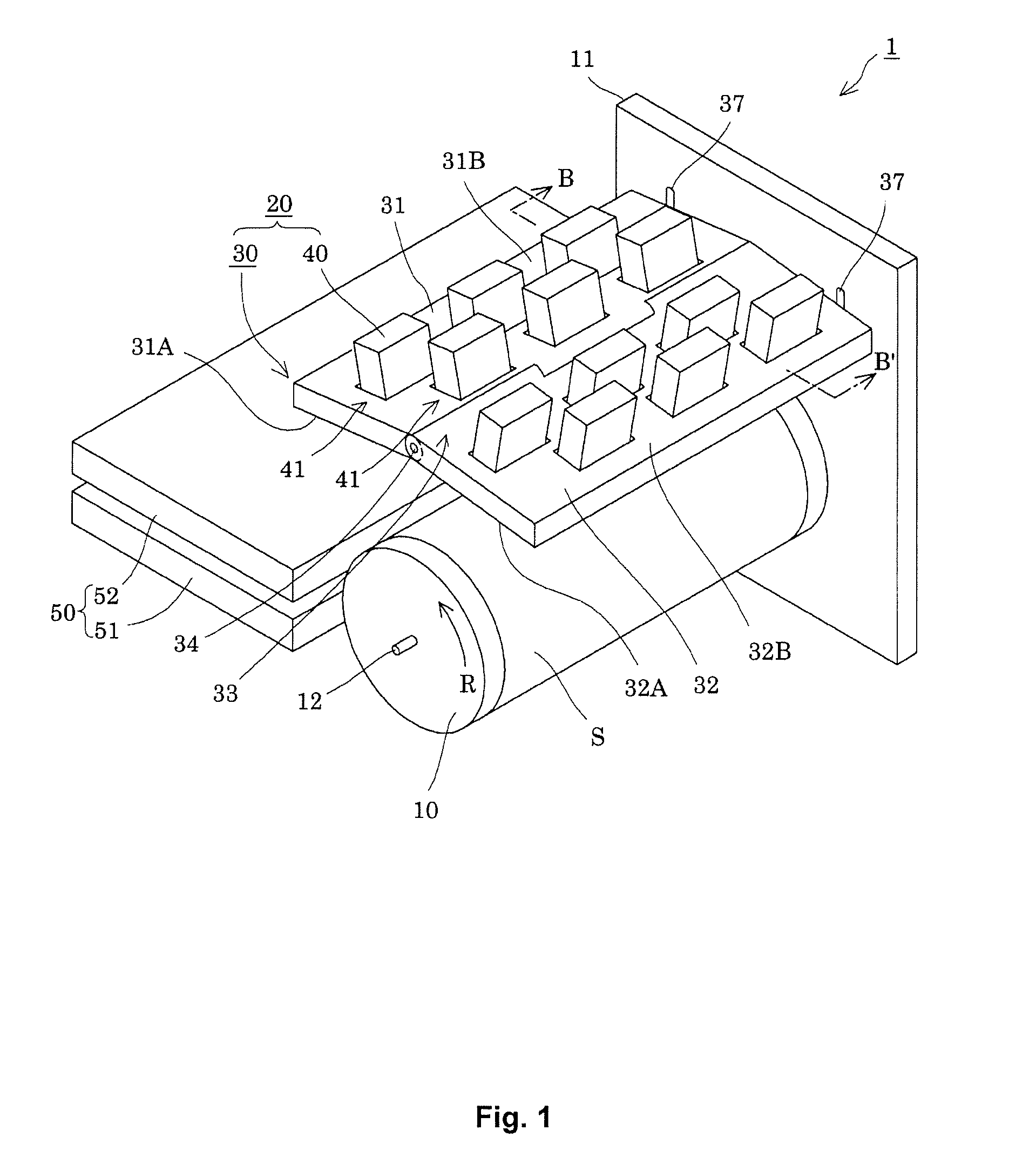
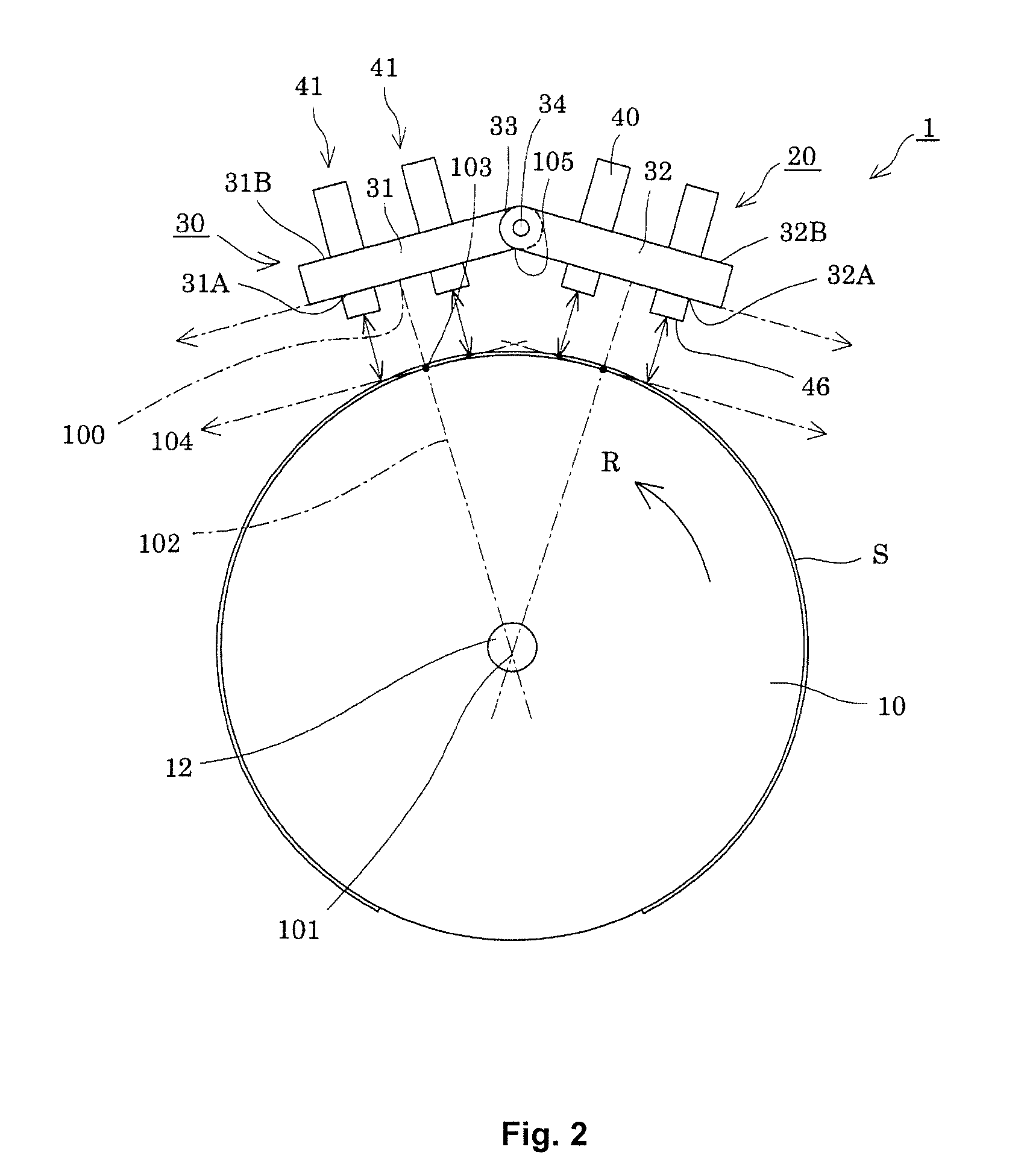
[0033]FIG. 1 is an overall perspective view showing the liquid ejection device according to an embodiment of the present invention, and FIG. 2 is a side view showing the relevant parts of the liquid ejection device. As shown in the drawings, the liquid ejection device 1 of the present embodiment is provided with a drum-shaped support drum 10, a liquid ejection head unit 20 provided on the external periphery of the support drum 10, and a conveyance means 50 which has a feeding part 51 for feeding an ejection-receiving medium S to the support drum 10 and a removal part 52 for removing the ejection-receiving medium S from the support drum 10.

[0034]The support drum 10 has a rotation shaft 12 supported by a frame 11, and the support drum 10 rotates about the rotation shaft 12 in the direction of the arrow R shown in FIG. 1. Such rotation of the support drum 10 is performed by a drive motor or other drive means n...


PUM

PropertyMeasurementUnit
angleaaaaaaaaaa
distancesaaaaaaaaaa
diameteraaaaaaaaaa

Abstract

A plurality of liquid ejection heads is attached to a head attachment member. The head attachment member is disposed so as to face a support drum for supporting an ejection-receiving medium and rotating about a shaft. The head attachment member includes a pair of plate-shaped members each having an attachment surface to which a plurality of head groups each including the liquid ejection heads is attached and a back surface extending parallel to the attachment surface. End parts of the plate-shaped members are connected to each other so as to be able to rotate about a hinge part so that an angle formed by the attachment surfaces is adjustable.

Description

CROSS-REFERENCE TO RELATED APPLICATIONS[0001]This application claims priority to Japanese Patent Application No. 2010-021685 filed on Feb. 2, 2010. The entire disclosure of Japanese Patent Application No. 2010-021685 is hereby incorporated herein by reference.BACKGROUND[0002]1. Technical Field[0003]The present invention relates to a head attachment member, a liquid ejection device, and a head attachment method, and is particularly useful for application to a liquid ejection device in which a liquid ejection head is attached so as to face a rotating support drum.[0004]2. Related Art[0005]Known liquid ejection devices for ejecting a liquid to an ejection-receiving medium include inkjet recording devices, for example, for ejecting ink as the liquid to print on a paper, recording sheet, or other ejection-receiving medium.[0006]Liquid ejection devices have been proposed in which an ejection-receiving medium is wound onto the periphery of a drum which rotates about a shaft, and printing i...

Claims


Application Information

Patent Timeline
Patent Type & Authority Patents(United States)
IPC IPC(8): B41J2/15B41J2/145
CPCB21D53/76B41J2/145Y10T29/49401B41J2025/008B41J2202/20B41J2/155B41J25/316B41J2202/21B41J25/34B41J2202/19B41J3/543B41J25/001B41J2/16585B41J2/1752
Inventor ISHII, HIROYUKIHAGIWARA, HIROYUKI
Owner SEIKO EPSON CORP
Why Eureka
Try Eureka