Wireless data transmitting and receiving system

a technology of transmitting and receiving system and wireless data, which is applied in the direction of position/direction control, non-deflectable wheel steering, vehicle position/course/altitude control, etc., and can solve the problem of affecting the tightening torque, increasing the transmission efficiency, and not being able to obtain accurate tightening torqu

Active Publication Date: 2012-09-11
MAEDA METAL IND LTD
View PDF8 Cites 81 Cited by
  • Summary
  • Abstract
  • Description
  • Claims
  • Application Information

AI Technical Summary

Benefits of technology

[0028]Moreover, transmitting the data from the data transmitting unit to the data receiving unit eliminates a connection object such as a signal line between the data transmitting unit and the data receiving unit. Accordingly, the workability is not adversely affected. Moreover, the influence by electric noise is less than that in a wired case.
[0029]Furthermore, since the display means is not necessary in the data transmitting unit, the data transmitting unit can be downsized and reduced in weight, and further, since a power source to operate the display means is not necessary, either, a battery as the power source can be downsized and have extended life.
[0030]In a tightening machine performing tightening by a torque method, since the tightening torque is directly detected from the rotary shaft, utilizing this tightening torque for control enables more accurate tightening by the torque method as compared with control by a current value of the power machine.
[0031]In a tightening machine performing tightening by a rotation-angle control method, since the rotation angle of the rotary shaft is directly detected, utilizing this rotation angle for control enables more accurate tightening by the rotation-angle control method as compared with control by the number of rotations of the rotary shaft of the power machine.
[0032]In a tightening machine performing tightening by a torque gradient method, the tightening toque and the rotation angle can be directly detected from the rotary shaft, a gradient of the torque to this rotation angle is detected, and variation of the value is utilized for control, which enables tightening by the primary torque gradient method, so that more accurate tightening by the torque gradient method can be performed as compared with control by detecting a gradient of the current value of the power machine to a tightening time to perform control in accordance with the variation of the value. Moreover, since the signals of the torque and the rotation angle can be transmitted from a single data transmitting unit, the torque and the rotation angle can be synchronized. Furthermore, since the rotation angle is also detected, a rotation speed can be detected from the tightening time and the rotation angle.
[0035]Furthermore, the receiving means is disposed in the tightening machine, and a setting switch is connected to the receiving means so that a desired tightening torque is inputted by the setting switch in advance, by which the received signal regarding the torque is fed back for the power control of the power machine of the tightening machine, and thereby, the bolt or the like can be tightened with the desired tightening torque. This enables more accurate tightening as compared with the torque detection by load sensing of the power machine or the like.

Problems solved by technology

In this method of detecting the current value to control the tightening torque, if the current value varies due to the variation of a voltage or the like, an accurate tightening torque cannot be obtained.
Furthermore, since force is transmitted to a rotary shaft from the power machine through a deceleration mechanism, the tightening torque is affected by a transmission efficiency of the deceleration mechanism.
That is, when the tightening machine continues to be used with a tightening torque to a current value of a new tightening machine, conformability is generated in the deceleration mechanism, which increases the transmission efficiency of the deceleration mechanism, resulting in too high a tightening torque to the same current value.
That is, since the tightening-torque measuring unit rotates integrally with the outer shaft, the display means cannot be sufficiently checked visually during rotation of the outer shaft or at some rotation stop positions of the outer shaft.
Moreover, the tightening-torque measuring unit is attached to the outer shaft side, and thus, when the actual tightening is performed by the inner shaft and the reaction force is received by the outer shaft, a difference between a torque acting on the outer shaft and a torque acting on the inner shaft actually performing the tightening may be caused.
However, since the tightening-torque measuring unit rotates together with the rotary shaft, the signal line may wind around the tightening-torque measuring unit, or may jam during working, which causes a possibility of disconnection.
Moreover, since in the signal line, electric noise is easily carried, it can be considered that the accurate torque value is not sent.
Although an electric-signal transmitting mechanism by a collector ring or the like can also be considered, the tightening-torque measuring unit itself is increased in size, leading to a deterioration of workability.

Method used


Image

  • Wireless data transmitting and receiving system
  • Wireless data transmitting and receiving system
  • Wireless data transmitting and receiving system

Examples


Embodiment Construction

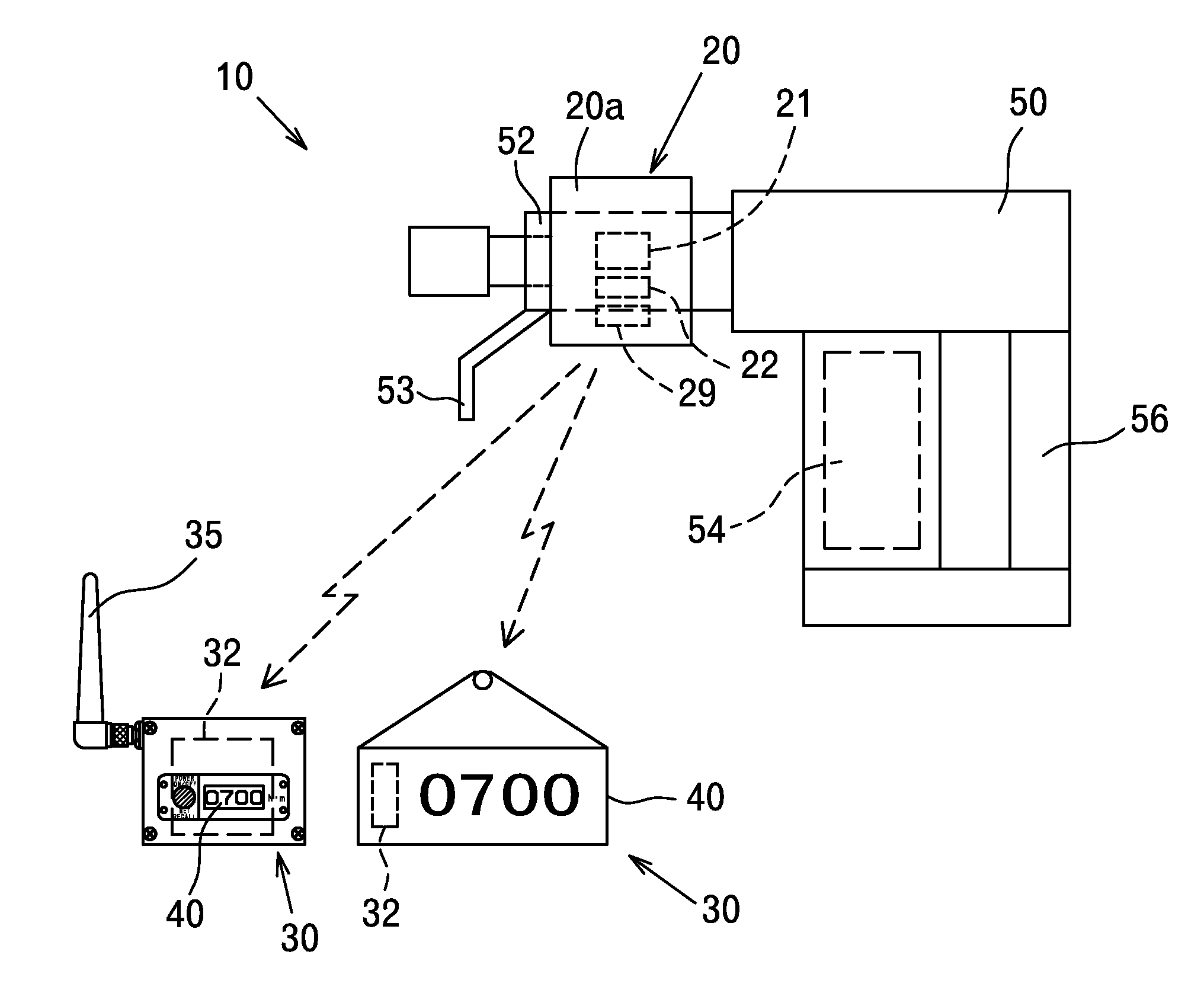
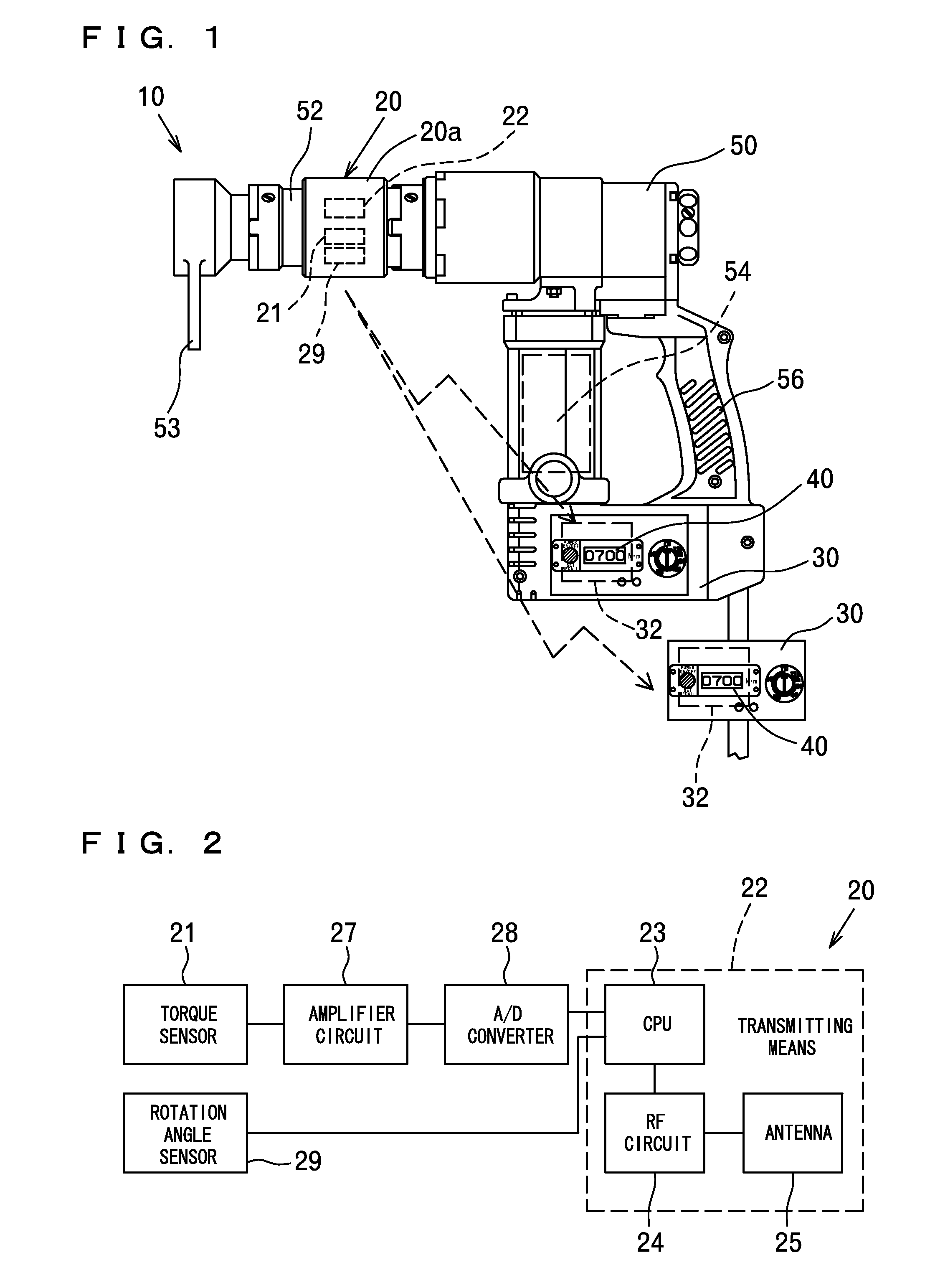
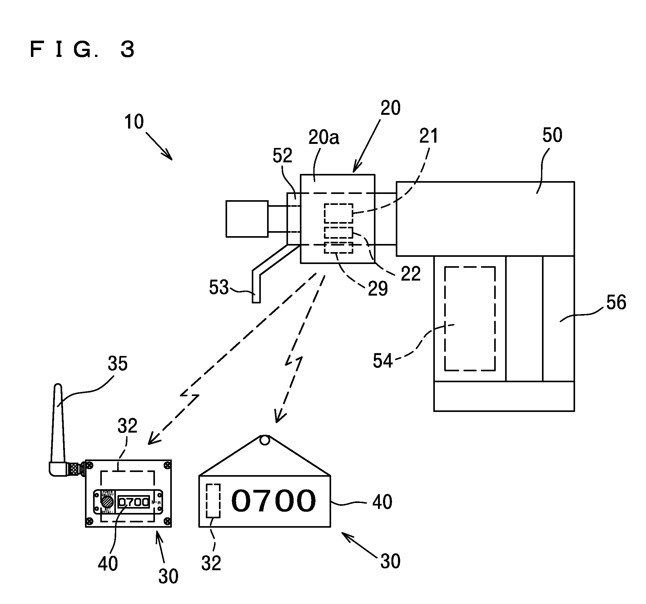
[0048]A wireless data transmitting and receiving system 10 of the present invention, as shown in FIG. 1, is made up of a data transmitting unit 20 disposed in a rotary shaft 52 of a tightening machine 50, and a data receiving unit 30 that receives a wireless signal regarding a torque from the data transmitting unit 20 to perform various operations.

[0049]In the present specification, the “rotary shaft”52 of the tightening machine 50, in the case of one shaft, includes a rotary shaft and various shafts that rotate accompanying the rotation thereof, and in the case of two shafts made of an inner shaft and an outer shaft as described in the background art, includes these shafts and various shafts that rotate accompanying the rotations thereof. A reaction force receiver 53 may be attached to the rotary shaft 52.

[0050]Moreover, while in the following description, the data transmitting unit 20 that can both detect a torque acting on the rotary shaft 52 and a rotation angle of the rotary sh...


PUM


Abstract

There is provided a wireless data transmitting and receiving system that wirelessly transmits a signal regarding a torque acting on a rotary shaft and / or a rotation angle of the rotary shaft from a data transmitting unit disposed in the rotary shaft to a data receiving unit. The wireless data transmitting and receiving system includes: a data transmitting unit (20) provided on the rotary shaft (52) of a tightening machine (50) to detect the torque and the rotation angle, the data transmitting unit (20) including a torque sensor (21) disposed so as to be capable of sensing a toque acting on the rotary shaft (52), a rotation angle sensor (29) disposed so as to be capable of a rotation angle of the rotary shaft (52), and transmitting means (22) that is electrically connected to the foregoing sensors (21,29), and wirelessly transmits signals regarding the torque detected in the torque sensor (21) and the rotation angle detected in the rotation angle sensor (29); and a data receiving unit (30) including receiving means (32) that receives the transmitted signals regarding the torque and the rotation angle, and display means (40) that displays the signals regarding the torque and the rotation angle received by the receiving means (32).

Description

BACKGROUND OF THE INVENTION[0001]1. Field of the Invention[0002]The present invention relates to a wireless data transmitting and receiving system that detects a torque and / or a rotation angle from a torque sensor and / or a rotation angle sensor disposed in a rotary shaft of a tightening machine to tight a bolt, a nut, a screw or the like, and wirelessly transmits the same to a data receiving unit.[0003]2. Description of the Related Art[0004]In a tightening machine that performs tightening by a torque method, a tightening torque is controlled by detecting a load of a power machine, that is, a current value of the power machine and using the current value as an index. In this method of detecting the current value to control the tightening torque, if the current value varies due to the variation of a voltage or the like, an accurate tightening torque cannot be obtained. Furthermore, since force is transmitted to a rotary shaft from the power machine through a deceleration mechanism, th...

Claims


Application Information

Patent Timeline
Patent Type & Authority Patents(United States)
IPC IPC(8): G08C15/00
CPCB25B21/00B25F5/00B25B23/14B25B13/488B25B23/0078B25B23/147G01L3/10G01L5/0095G08C19/38G08C25/02
Inventor OBATAKE, TAKAYOSHIKANEYAMA, YASUNOBUKUSHIDA, TOSHIHIKOHIRAI, TATSUO
Owner MAEDA METAL IND LTD
Why Eureka
Try Eureka