Interlocking platform panels and modules

a technology of interlocking platforms and modules, applied in the direction of flooring, walls, treads, etc., can solve the problem that none of these flooring systems are designed for installation over a conventional joist substructure, and achieve the effect of adding the ability of fastening

Inactive Publication Date: 2012-09-18
MCFARLAND CASCADE HLDG
View PDF45 Cites 35 Cited by
  • Summary
  • Abstract
  • Description
  • Claims
  • Application Information

AI Technical Summary

Benefits of technology

[0014]The composition of the platform panel or module and its placement of panel- or module-coupling clips and vertical and horizontal fasteners makes it easy to trim the platform panel or module into virtually any shape and still attach it to the substructure.
[0015]Each platform panel or module also incorporates a plurality of additional molded, pultruded, stamped, or riveted features. For example, each platform panel or module includes a lattice structure of reinforcing ribs that increase the structural strength of the platform panel or module while minimizing its overall weight. Each platform panel or module also includes male connectors (such as clips or tabs) that engage corresponding female receptacles of an adjacent platform panel or module. Also, small 3 mm (⅛ inch) ribs on the sides of the panel or module establish an exact and consistent spacing between adjacent panels or modules to allow for water drainage and air circulation.
[0017]Large horizontal tabs on one side of each platform panel include two holes or indentations for screws, nails, or other fasteners that positively attach the panel to the joist substructure and restrict movement in the vertical and horizontal directions. Diagonal holes or indentations incorporated in various locations, including the panel- or module-coupling and joist-spanning sides, provide additional fastening capability.

Problems solved by technology

None of these flooring systems are designed for installation over a conventional joist substructure.

Method used


Image

  • Interlocking platform panels and modules
  • Interlocking platform panels and modules
  • Interlocking platform panels and modules

Examples


Embodiment Construction

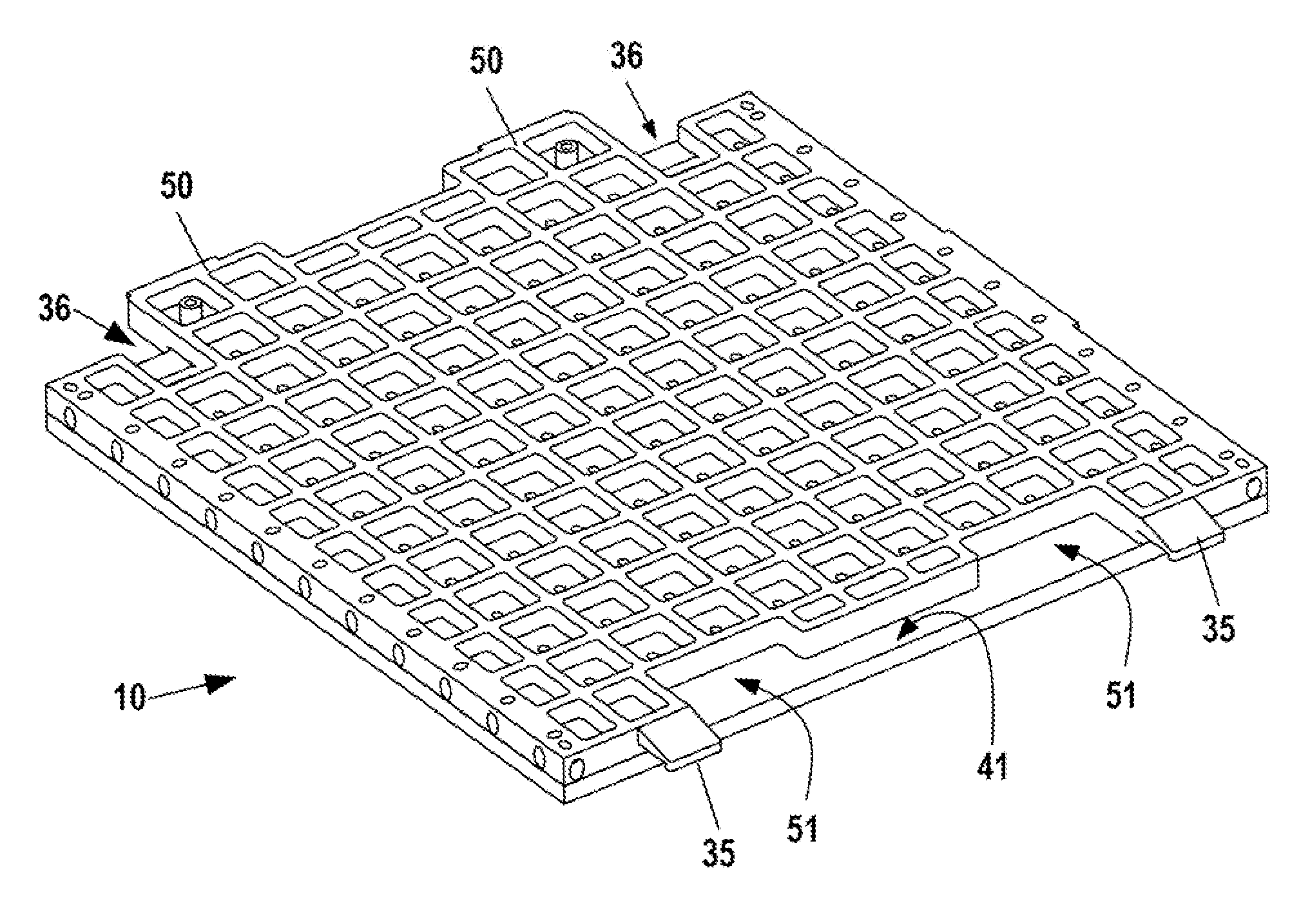
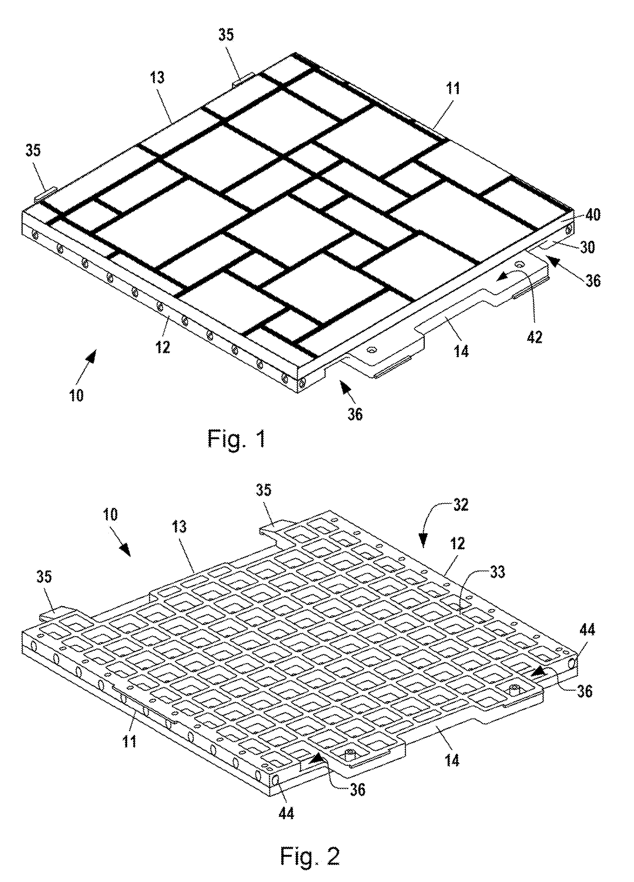
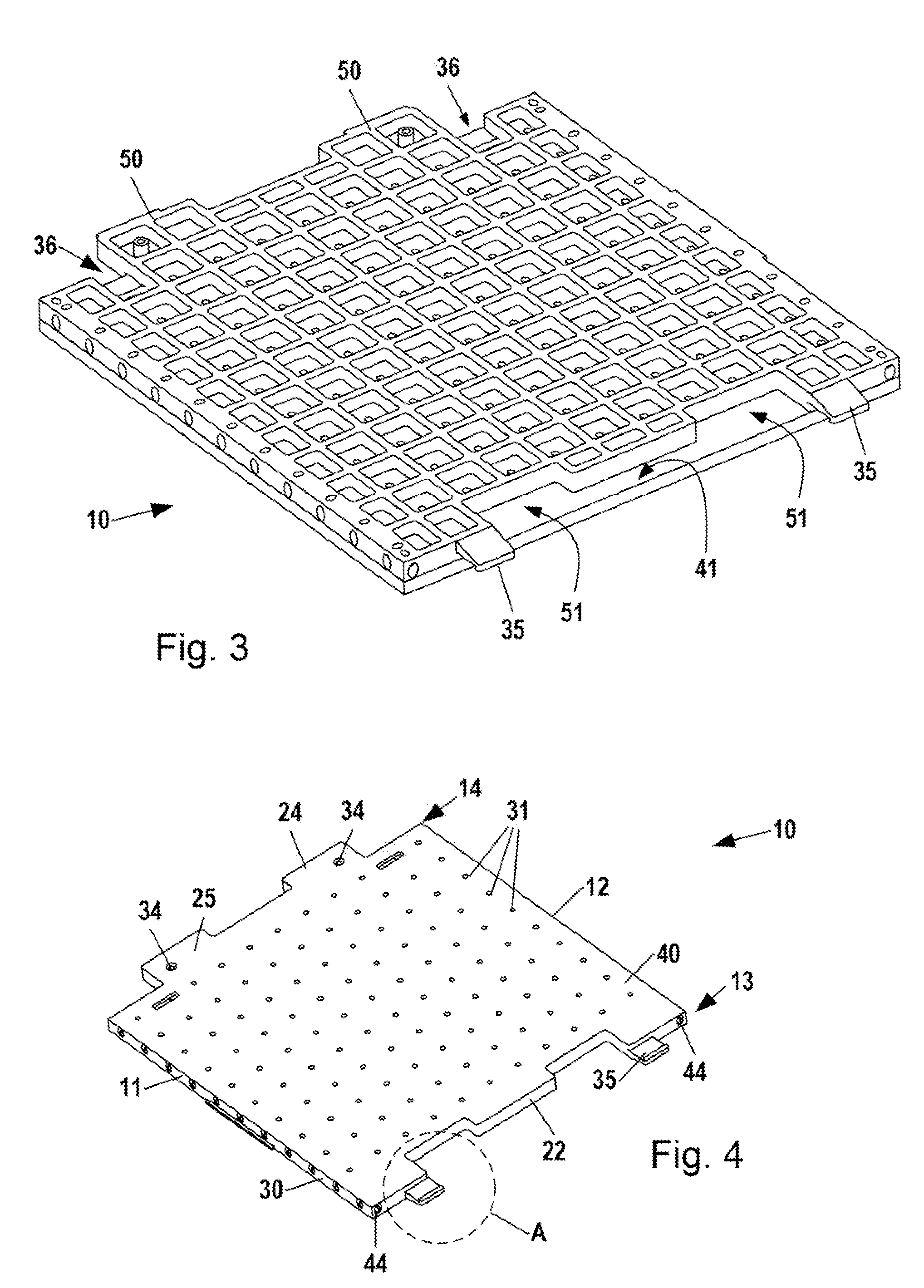
[0100]In describing preferred and alternate embodiments of the technology described herein, as illustrated in FIGS. 1-82, specific terminology is employed for the sake of clarity. The technology described herein, however, is not intended to be limited to the specific terminology used, and it is to be understood that each specific element includes all technical equivalents that operate in a similar manner to accomplish similar functions.

[0101]FIGS. 1-82 illustrate various embodiments of a surface platform panel or module 10 according to the present invention. Most of these drawings illustrate surface platform panels or modules 10 with general dimensions of approximately 406 mm (16 inches) by 445 mm (17.5 inches) by 15 mm (0.6 inches), which are particularly suitable for 16-inch (406 mm) off-center joist substructures 90. The invention, however, encompasses platform panels or modules 10 with other dimensions, shapes, and configurations.

[0102]The platform panel or module 10 is particul...


PUM

PropertyMeasurementUnit
widthaaaaaaaaaa
diameteraaaaaaaaaa
diameteraaaaaaaaaa

Abstract

A platform panel or module is provided to construct a surface for a deck, floor, wall, ceiling, or roof. The panel or module comprises a decorative top layer integral with or joined to a structural, composite molded platform. Each platform panel or module has two complementary module-coupling sides that take advantage of the full width of each joist that supports the platform. Also, male and female connecting members are disposed along the module-coupling sides that enable one platform panel or module to be efficiently and positively interlocked with an adjacent panel or module. Each panel or module can be fastened on one side to a single joist while being secured on its opposite side to an adjoining panel or module. The panels or modules are also designed to cover over an entire joist substructure, including the beginning-of-sequence and end-of-sequence joists.

Description

RELATED APPLICATIONS[0001]This application claims the benefit of, and hereby incorporates by reference, our earlier U.S. provisional patent application Nos. 61 / 181,439, filed May 27, 2009 and entitled “Interlocking Platform Surfacing System,” and 61 / 232,182, filed Aug. 7, 2009, entitled “System of Modular Surface Platform Panels.”FIELD OF THE INVENTION[0002]This invention relates generally to deck, floor, ceiling, wall, and roof surfaces, and in particular, to modular surface platforms and panels mounted on an underlying substructure to form the surface of a deck, floor, wall, ceiling, or roof.BACKGROUND OF THE INVENTION[0003]The prior art discloses numerous systems for creating the surface of a deck, floor, ceiling, wall, or roof. A significant category of this prior art utilizes pre-assembled or modular panels or sections to form the desired surface.[0004]Many references disclose modular flooring systems intended for installation on a flat subfloor. U.S. Pat. No. 4,170,859 to Coun...

Claims


Application Information

Patent Timeline
Patent Type & Authority Patents(United States)
IPC IPC(8): E04F11/16
CPCE04F15/02E04F15/10E04F2201/0107E04F2201/091E04F2201/096E04F15/02194E04F15/043E04F15/087E04F15/105
Inventor BRAVO, VICTOR LEONELDOCTER, LLOYD WILSON
Owner MCFARLAND CASCADE HLDG
Why Eureka
Try Eureka