
Cup for holding bottles in a bottle rack

a bottle rack and bottle cup technology, applied in the field of bottle supports, can solve the problems of difficulty in reading labels, a large amount of undesirable lateral movement of bottles in the bottle rack, and the majority of attempts to achieve such movements, etc., and achieve the effect of being easily integrated into common building materials

Inactive Publication Date: 2012-09-18
WUNDERWALL
View PDF36 Cites 9 Cited by
  • Summary
  • Abstract
  • Description
  • Claims
  • Application Information

AI Technical Summary

Benefits of technology

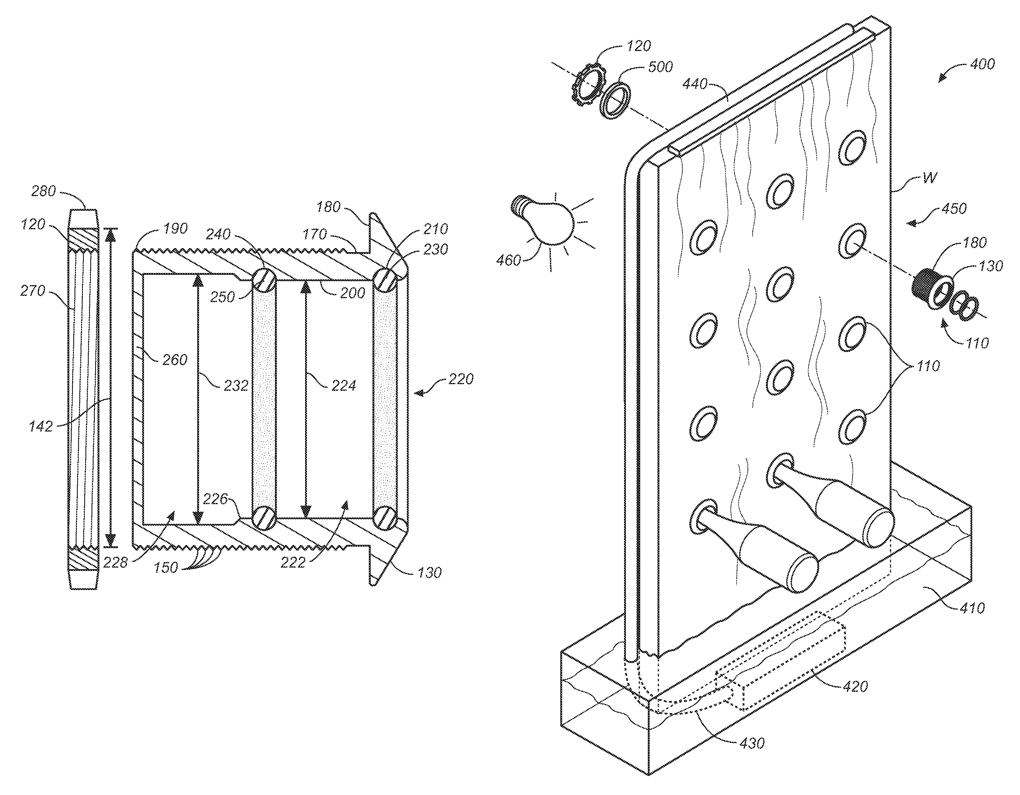
[0020]The inventive apparatus in its most essential aspect is a modular receptacle formed from a rigid cylindrical piece that may be easily incorporated into common building materials. It can be disposed in an array comprising a plurality of receptacles so as to permit easy access to a number of bottles and easy viewing of a number of bottle labels. The receptacle includes resilient insert rings or gaskets disposed on the interior side of the receptacle to protect foil caps from damage and to prevent bottle movement both vertically and horizontally. Carefully engineered inner dimensions ensure that bottles are held rigidly in position by the force of gravity. However, a bottle may be removed from the rack simply by lifting the exposed end of the bottle and withdrawing the bottle from the receptacle.

Problems solved by technology

What may not be readily appreciated from a cursory review of the above-identified patents is that prior art bottle supports utilizing non-engineered, circular apertures allow a considerable amount of undesirable lateral movement of bottles.
Most such attempts, however, have been largely unsuccessful owing to the fact that the third point is positioned in the same vertical plane as the original two points with respect to the longitudinal axis of the bottle.
In addition, the steep angles required cause any sediment in wine bottles to settle in the neck and against the cork and present wine labels in an upside down orientation, which causes some difficulty in reading the labels.
But it will be appreciated that repeated insertion and removal of bottles causes a deterioration in the integrity of the structure.
But this adds considerable mass to the support structure.

Method used


Image

  • Cup for holding bottles in a bottle rack
  • Cup for holding bottles in a bottle rack
  • Cup for holding bottles in a bottle rack

Examples


Embodiment Construction

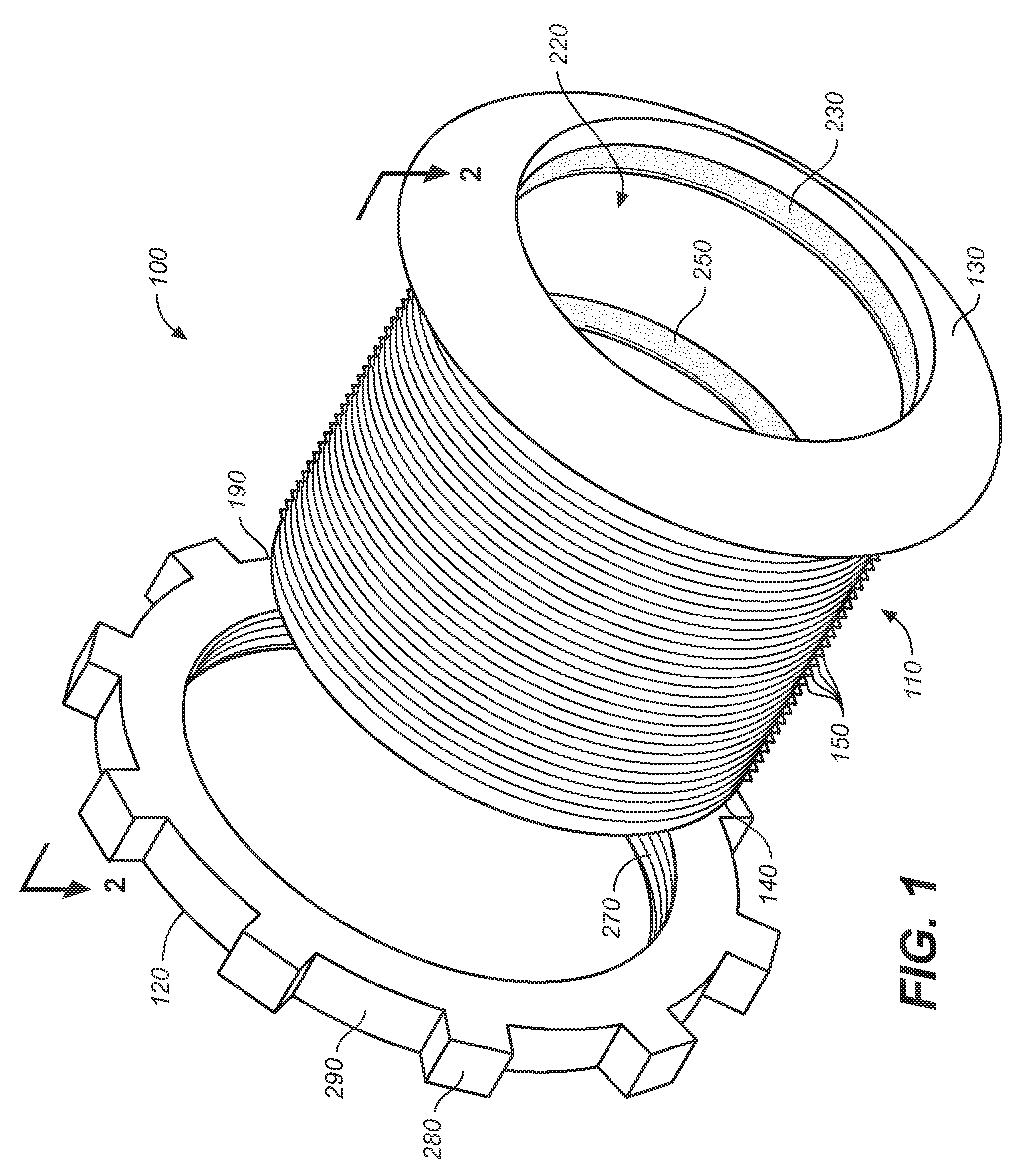
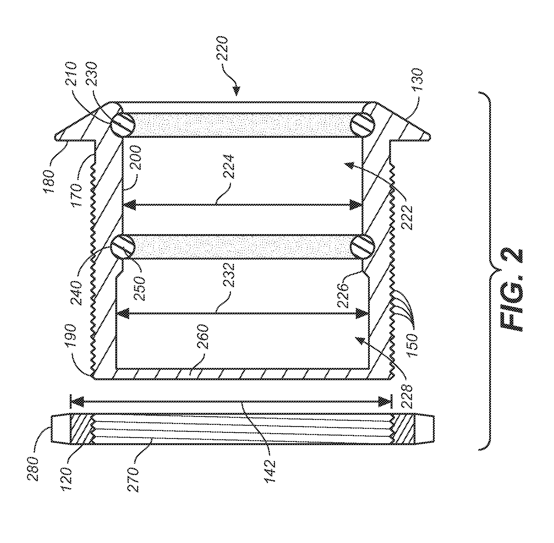
[0030]Referring first to FIGS. 1 through 4, wherein like reference numerals refer to like components in the various views, there is illustrated therein a new and improved cup for holding bottles in a bottle rack, generally denominated 100 herein.

[0031]Referring first to FIGS. 1-2, the inventive cup of the present invention most essentially includes a receptacle portion 110 and a locking nut 120. The receptacle portion includes a beveled outer flange 130 and a cylindrical body 140 having male threads 150 disposed on its exterior side 160 and extending from a point 170 proximate the outer flange underside 180 to the inner end 190 of the cylindrical body. In a preferred embodiment, the outer diameter 142 of the cylindrical body may taper slightly from the outer flange underside to the inner end, such that the outer diameter of the cylindrical body at the inner end is slightly smaller than the outer diameter near or at the underside of the outer flange. This facilitates placement of the...


PUM

PropertyMeasurementUnit
diameteraaaaaaaaaa
resilientaaaaaaaaaa
gravityaaaaaaaaaa

Abstract

A cup-shaped receptacle designed to engage the neck of a bottle and rigidly support it in a near horizontal position. The receptacle can be incorporated into many common building materials, so an array of the receptacles permits an attractive display of bottles. Bottles are held in place through the force of gravity and by resilient rings or gaskets disposed in the interior of the receptacle that limit vertical and horizontal migration of bottles. The rings also protect foil caps from damage.

Description

CROSS REFERENCES TO RELATED APPLICATIONS[0001]The present application claims the benefit of U.S. Provisional Patent Application Ser. No. 61 / 169,043, filed Apr. 14, 2009 (Apr. 14, 2009).STATEMENT REGARDING FEDERALLY SPONSORED RESEARCH OR DEVELOPMENT[0002]Not applicable.THE NAMES OR PARTIES TO A JOINT RESEARCH AGREEMENT[0003]Not applicable.INCORPORATION-BY-REFERENCE OF MATERIAL SUBMITTED ON A COMPACT DISC[0004]Not applicable.SEQUENCE LISTING[0005]Not applicable.BACKGROUND OF THE INVENTION[0006]1. Field of the Invention[0007]The present invention relates generally to bottle supports, and more particularly to a bottle holding apparatus for holding a bottle exclusively by its neck, thereby displaying the bottle front below the shoulder. Still more particularly, the present invention relates to a rigid removable cup for installation in a wall or other structural substrate that includes resilient internal rings for cushioning and protecting the bottle during storage. The invention can be u...

Claims


Application Information

Patent Timeline
Patent Type & Authority Patents(United States)
IPC IPC(8): A47B73/00A47F5/08
CPCA47B73/004Y10T29/49826
Inventor FISHER, ROBERT E.THOMPSON, ROBERT W.
Owner WUNDERWALL
Learn More