Cutting insert having a corner recess

a cutting insert and corner recess technology, applied in the field of cutting inserts, can solve the problems of requiring a serrated cutting insert, workpiece and tool damage, etc., and achieve the effects of reducing the cutting load, effective control of chips, and low feed ra

Inactive Publication Date: 2012-09-18
TAEGUTEC
View PDF7 Cites 17 Cited by
  • Summary
  • Abstract
  • Description
  • Claims
  • Application Information

AI Technical Summary

Benefits of technology

[0017]The cutting insert according to the present invention having the structure and function as described above can control the chips effectively and minimize a cutting load under the machining conditions of a low feed rate and a high depth of cut.
[0018]In addition, the thin chip generated on a cutting surface of the work-piece which is contacted with the side cutting edge portion can be wrinkled due to the side cutting edge portion having the serration shape so that the wrinkled chip can be broken easily.

Problems solved by technology

Consequently, the work-piece and the tool may be damaged by the chips.
In particular, to machine mild steel generating chips which are difficult to control (that is, not bent easily), the serrated cutting insert is required.

Method used


Image

  • Cutting insert having a corner recess
  • Cutting insert having a corner recess
  • Cutting insert having a corner recess

Examples


Embodiment Construction

[0027]Hereinafter, the present invention is described in detail with reference with the accompanying drawings.

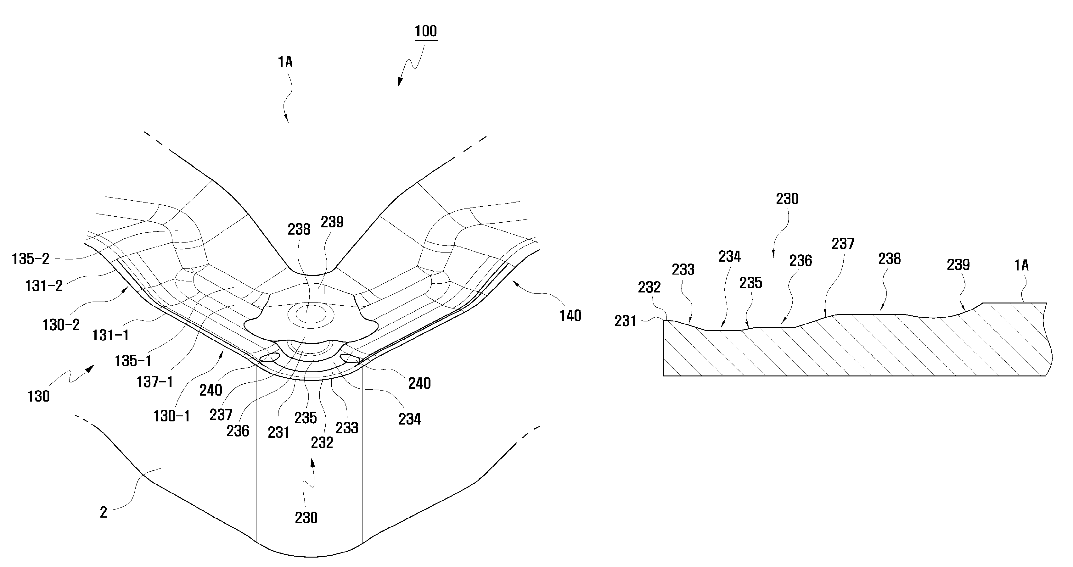
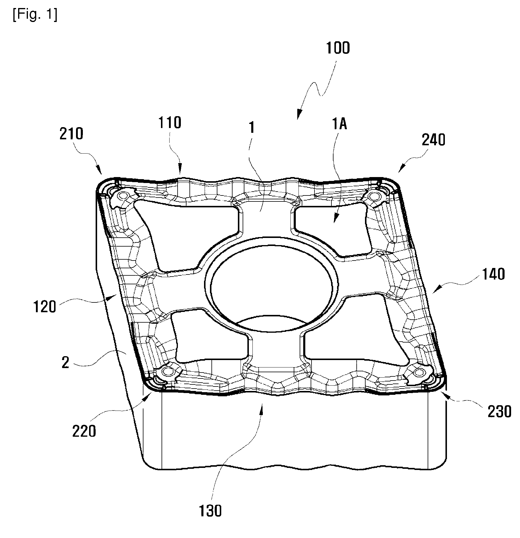
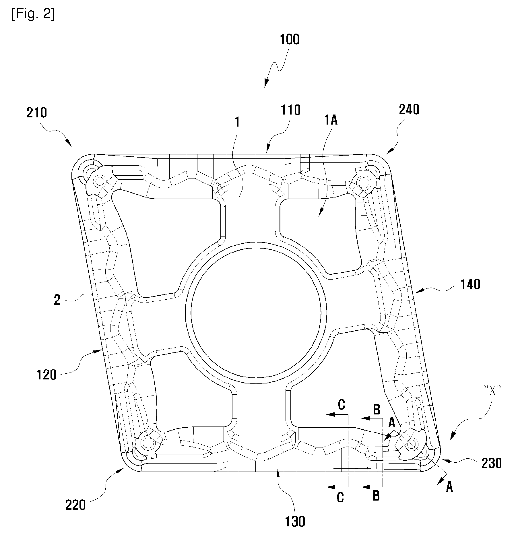
[0028]FIG. 1 and FIG. 2 are perspective view and plane view of a cutting insert according to the present invention and show a cutting insert having a structure being capable of controlling effectively chips generated on a work-piece.

[0029]A cutting insert 100 includes an upper surface 1, a lower surface and side surfaces 2, each of four (4) side cutting edge portions 110, 120, 130 and 140 is formed at an intersection between the upper surface 1 (or the lower surface) and the side surface 2. In addition, each of four (4) edge corner portions 210, 220, 230 and 240 is formed at an intersection between two adjacent side edge portions. A central hole is formed at the central portion of the insert.

[0030]As an example, the cutting insert 100 is an equilateral parallelogram member having a certain angled diamond shape. That is, as shown in FIG. 2, one side surface 2 of the cutting i...


PUM

PropertyMeasurementUnit
heightaaaaaaaaaa
heightaaaaaaaaaa
heightaaaaaaaaaa

Abstract

A cutting insert for a machining tool has a structure capable of effectively controlling chips generated on a work-piece. The cutting insert includes an upper surface, a lower surface, a plurality of side surfaces connecting the upper surface and the lower surface and a central hole formed at a central portion thereof. In the cutting insert, a seating surface is formed on a highest portion of the upper surface, a plurality of side cutting edge portions are formed at border portions of the upper surface and the side surfaces. Each side cutting edge portion has a side cutting edge formed at an upper end thereof and a corner cutting edge portion is formed at an intersection of two adjacent side cutting edge portions. The corner cutting edge portion has a cutting edge formed at a front end thereof, a land portion, a downward inclined surface, a corner bottom surface, a first upward inclined surface, a first protrusion, a second upward inclined surface, a second protrusion, an upward grooved surface and the seating surface sequentially formed along a diagonal line directed from the corner cutting edge toward the central hole. The corner bottom surface has the smallest height along the diagonal line.

Description

TECHNICAL FIELD[0001]The present invention relates to a cutting insert, more particularly, to a cutting insert having a structure being capable of effectively controlling chips generated on a work-piece at the time of performing a cutting process for the work-piece.BACKGROUND ART[0002]In general, a machining tool is used in the field of cutting machining such as drilling, milling, and turning. Within the fields of drilling and milling, a tool having a rotary character is useful for machining a fixed and movable work-piece.[0003]On the contrary, a machining tool for turning machining is fixed and has the purpose of machining work-piece which is rotating. In general, the machining tool comprises a tool holder and a cutting insert fixed to a mounting surface of the tool holder through a clamping means and contacted with the work-piece.[0004]When a turning machining in which the machining tool is utilized is performed, chips generated on the work-piece by the cutting insert should be se...

Claims


Application Information

Patent Timeline
Patent Type & Authority Patents(United States)
IPC IPC(8): B23B27/22B23B27/00
CPCB23B27/143B23B2200/0428B23B2200/081B23B2200/085B23B2200/161Y10T407/23B23B2200/205B23B2200/321B23B2200/323Y10T407/235B23B2200/163B23B27/04B23B27/02
Inventor PARK, HONG SIKNA, BO RA
Owner TAEGUTEC
Why Eureka
Try Eureka