
Method and apparatus for MRI signal excitation and reception using non-resonance RF method (NORM)

a mri signal and non-resonance technology, applied in the field of mri signal excitation and reception using non-resonance rf method, can solve the problems of reducing the efficiency of mr signal excitation and reception, etc., to achieve the effect of reducing current fluctuations

Active Publication Date: 2012-09-18
RGT UNIV OF CALIFORNIA
View PDF7 Cites 21 Cited by
  • Summary
  • Abstract
  • Description
  • Claims
  • Application Information

AI Technical Summary

Problems solved by technology

However, the resonance requirement of RF coils creates many experimental complexities and technical challenges particularly in designing high and ultrahigh field (3T and above) coils, double or multiple-tuned coils and parallel imaging arrays.
These technical difficulties / challenges dramatically hinder the development and the use of MR imaging due to the low RF coil quality, significantly reducing efficiency of the MR signal excitation and reception.
One example is that in designing large-sized RF coils for high field MR imaging it is extremely difficult (or impossible) to achieve the required high resonant frequency due to the increased self-inductance and parasitic capacitance of the RF coils.
Another example is that in designing RF coil arrays for parallel imaging, a daunting technical challenge is to attain sufficient electromagnetic decoupling among the resonant elements in coil arrays.
Insufficient decoupling results in low efficiency of RF coil arrays, ultimately leading to low parallel imaging performance.
With existing methods, it is extremely difficult to design RF coils for high field human MR imaging at high resonant frequencies due to the increased self-inductance and parasitic capacitance present with conventional RF coils.
Coils for such applications generally are large and thus difficult to design and build to achieve the required high operating frequency.

Method used


Image

  • Method and apparatus for MRI signal excitation and reception using non-resonance RF method (NORM)
  • Method and apparatus for MRI signal excitation and reception using non-resonance RF method (NORM)
  • Method and apparatus for MRI signal excitation and reception using non-resonance RF method (NORM)

Examples


Embodiment Construction

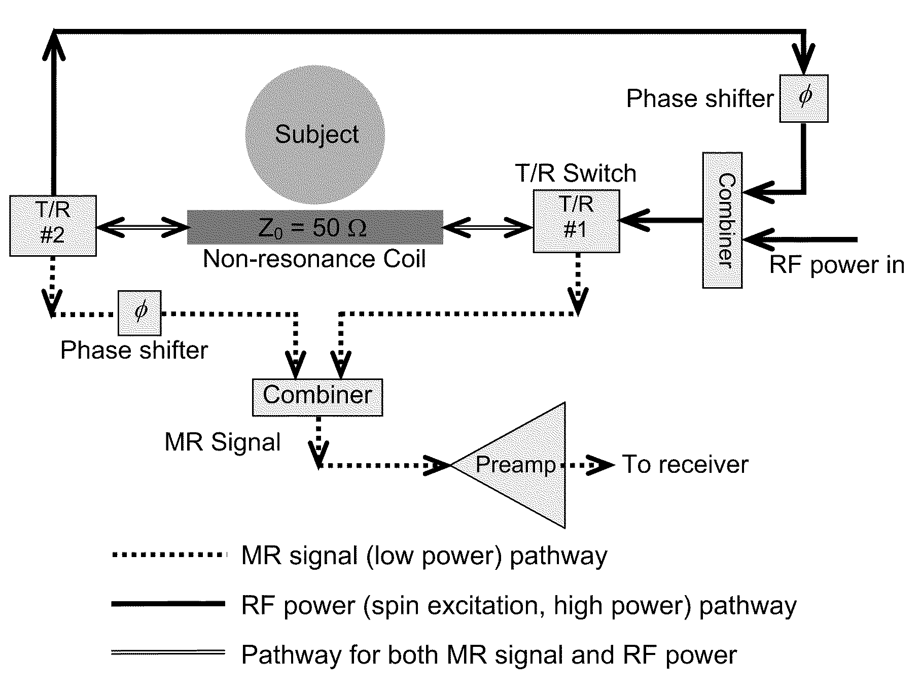
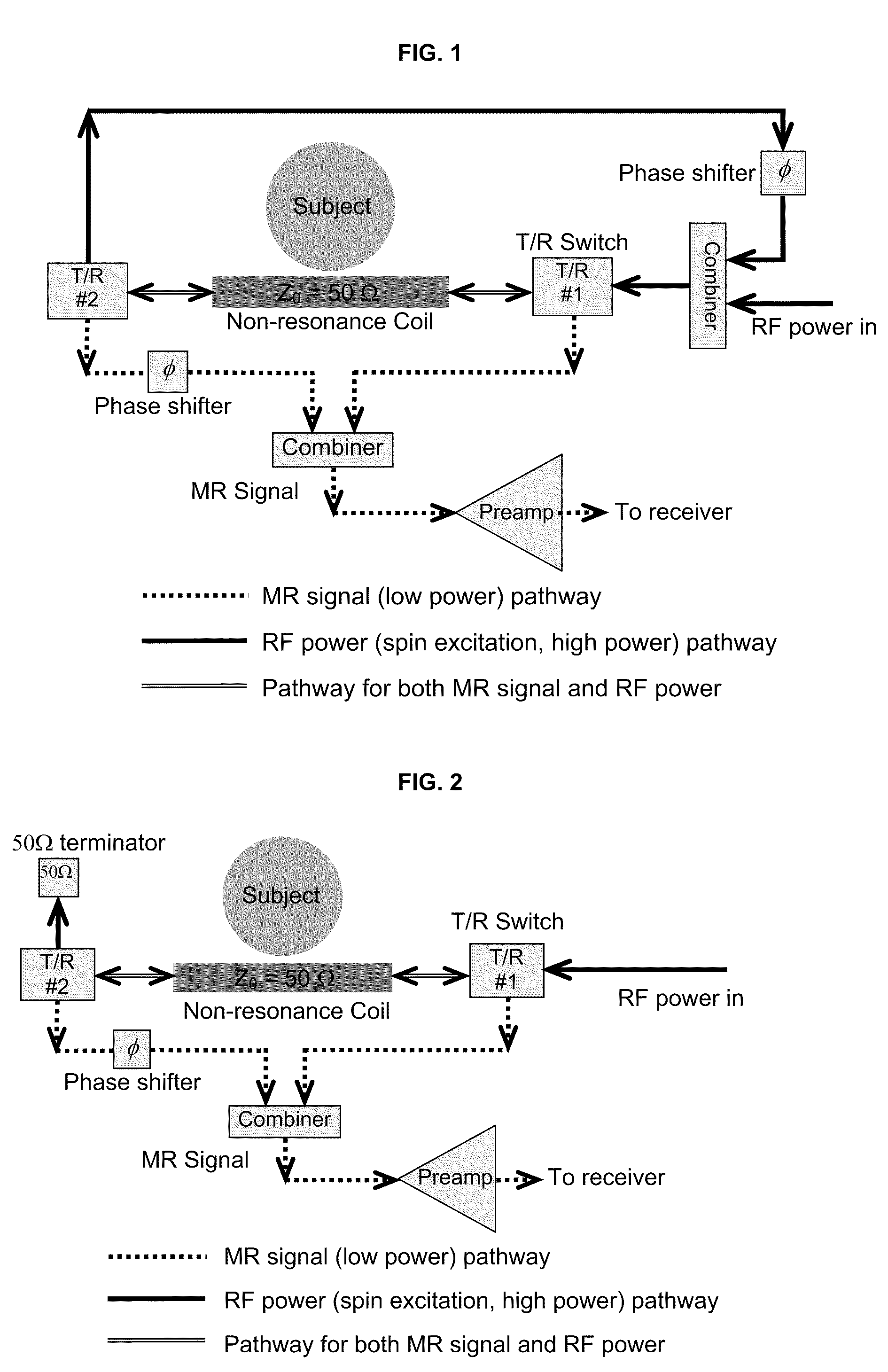
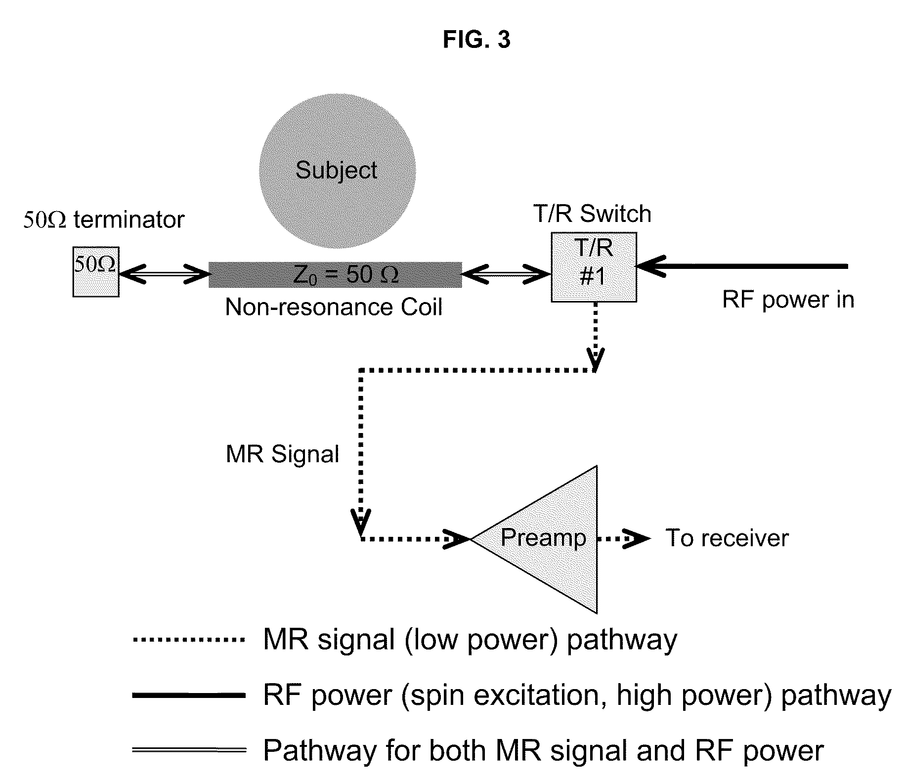
[0020]The present inventions are directed to an RF coil solution using non-resonance RF coils for MR imaging and spectroscopy. “RF coil” is used herein to describe a device for creating an RF signal for MR imaging and includes, but is not limited to, conductive coils, microstrip transmission lines, and other RF devices as would be understood in the field of radiology and MR research. The non-resonance coil technique significantly simplifies the RF coil design and also overcomes numerous RF technical difficulties in designing high frequency coils, multiple tuned coils (for multi-nuclear MR applications) and parallel imaging coil arrays. We have demonstrated the non-resonance coil technology by 1H MR images, and 31P, 23Na and 13C spectra acquired using the non-resonant coil and the coil array. MR sensitivity (or signal-to-noise ratio, SNR) comparison has been also performed between the non-resonant coils and conventional resonant coils.

[0021]In various respects, the present invention ...


PUM


Abstract

A system for MR signal excitation and reception and method which uses a non-resonant device or transmission line to perform MR imaging and spectroscopy. The system with non-resonant device is advantageous to parallel imaging due to the improved decoupling performance. Because the non-resonant RF coil is not generally sensitive to frequency, a MR system with the non-resonant RF coil is capable of multinuclear MR operation at varied magnetic field strength. The system comprises a non-resonant RF coil for connecting to an MR system, the conductor being configured to have a characteristic impedance matched to the MR system. The RF coil is configured to produce electromagnetic fields of differing strengths based on the constant characteristic impedance maintained in the system for exciting and receiving MR signals.

Description

CROSS-REFERENCES TO RELATED APPLICATIONS[0001]This application claims priority under 35 U.S.C. §119(e) to U.S. Provisional Application No. 61 / 175,426 filed May 4, 2009, the entire contents of which are incorporated herein by this reference for all purposes.STATEMENT AS TO RIGHTS TO INVENTIONS MADE UNDER FEDERALLY SPONSORED RESEARCH AND DEVELOPMENT[0002]This invention was made with government support under Grant No. EB 004453 awarded by the National Institutes of Health. The government has certain rights in the invention.BACKGROUND[0003]Conventionally, magnetic resonance (MR) signals are excited and received by an RF resonator comprised of an RF coil resonating at Larmor frequency. MR experiments with different nuclei or at different static field strengths usually require different RF coils which resonate at a desired frequency or frequencies. Since the discovery of the MR phenomena, resonant RF coils have generally been used for MR signal excitation and reception. Functioned as a fi...

Claims


Application Information

Patent Timeline
Patent Type & Authority Patents(United States)
IPC IPC(8): G01V3/00
CPCG01R33/3415G01R33/3628G01R33/34046G01R33/341G01R33/3453G01R33/3456
Inventor ZHANG, XIAOLIANG
Owner RGT UNIV OF CALIFORNIA
Learn More