Multi-pane electrochromic windows

a multi-pane, electrochromic window technology, applied in the direction of ohmic-resistance heating, door/window protective devices, instruments, etc., can solve the problems of high defectivity, conventional electrochromic windows, and various problems of electrochromic devices, so as to achieve the effect of improving defectivity

a multi-pane, electrochromic window technology, applied in the direction of ohmic-resistance heating, door/window protective devices, instruments, etc., can solve the problems of high defectivity, conventional electrochromic windows, and various problems of electrochromic devices, so as to achieve the effect of improving defectivity

US8270059B2Active Publication Date: 2012-09-18VIEW INC

Image

  • Multi-pane electrochromic windows
  • Multi-pane electrochromic windows
  • Multi-pane electrochromic windows

Examples


Embodiment Construction

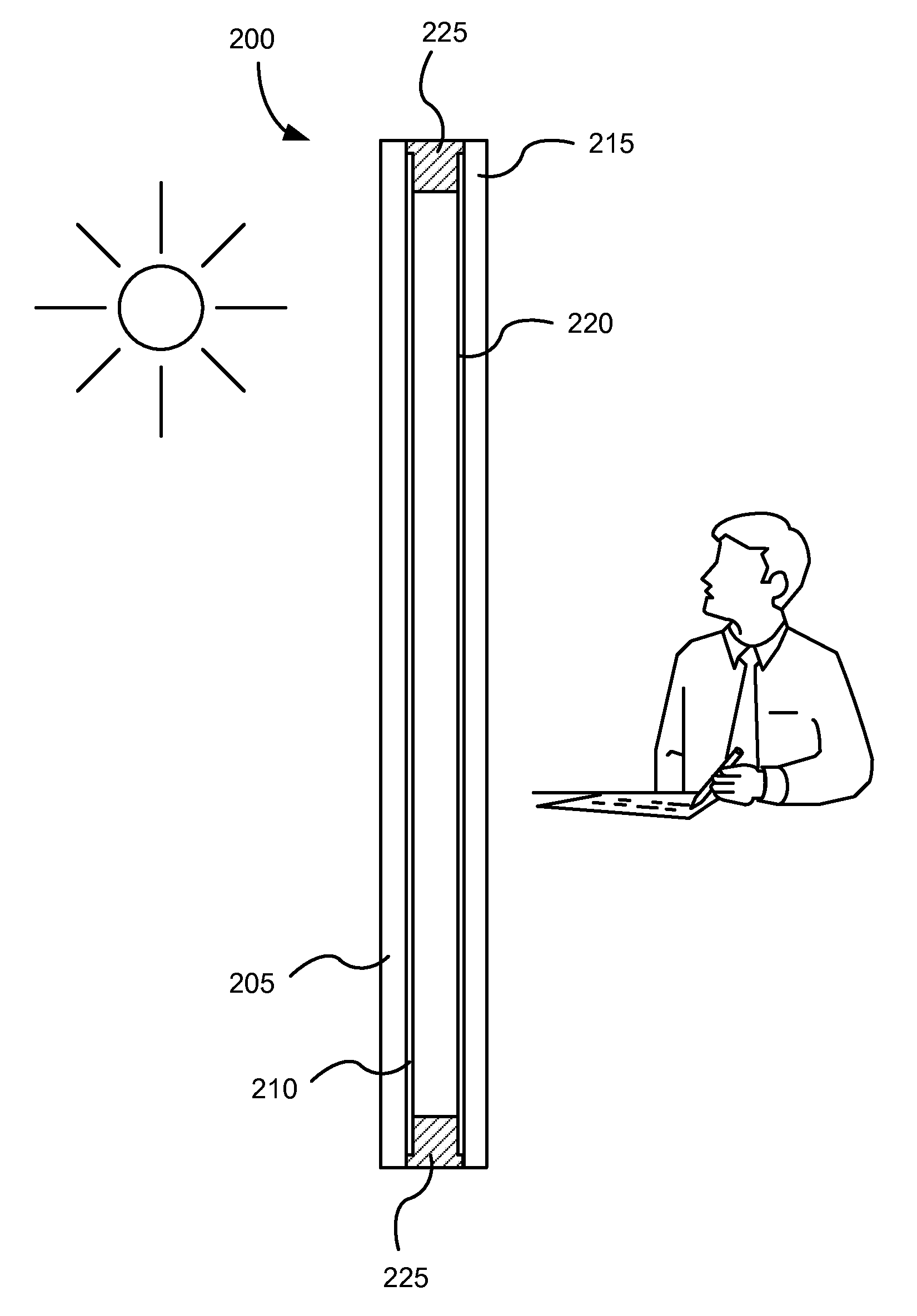
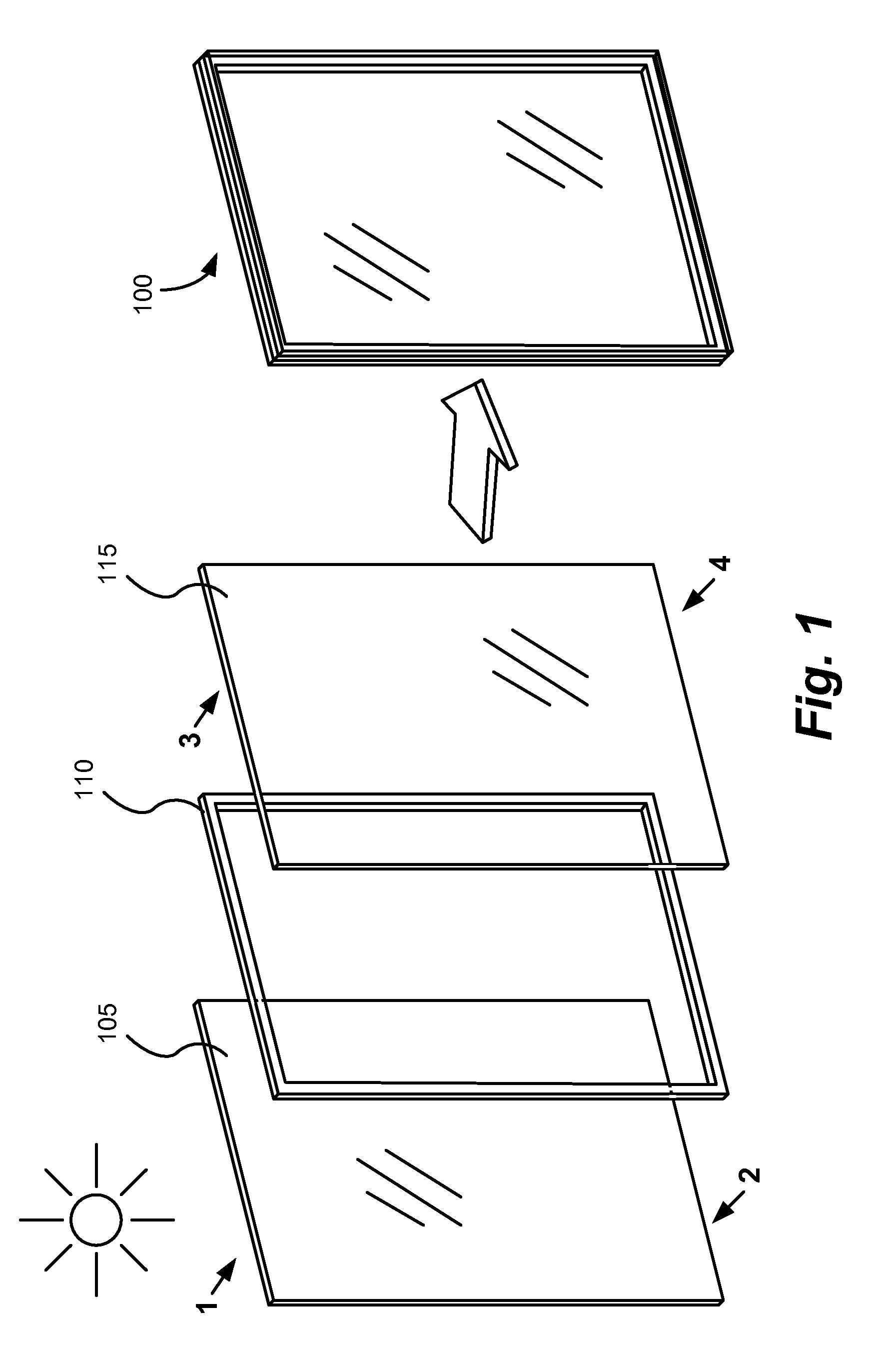
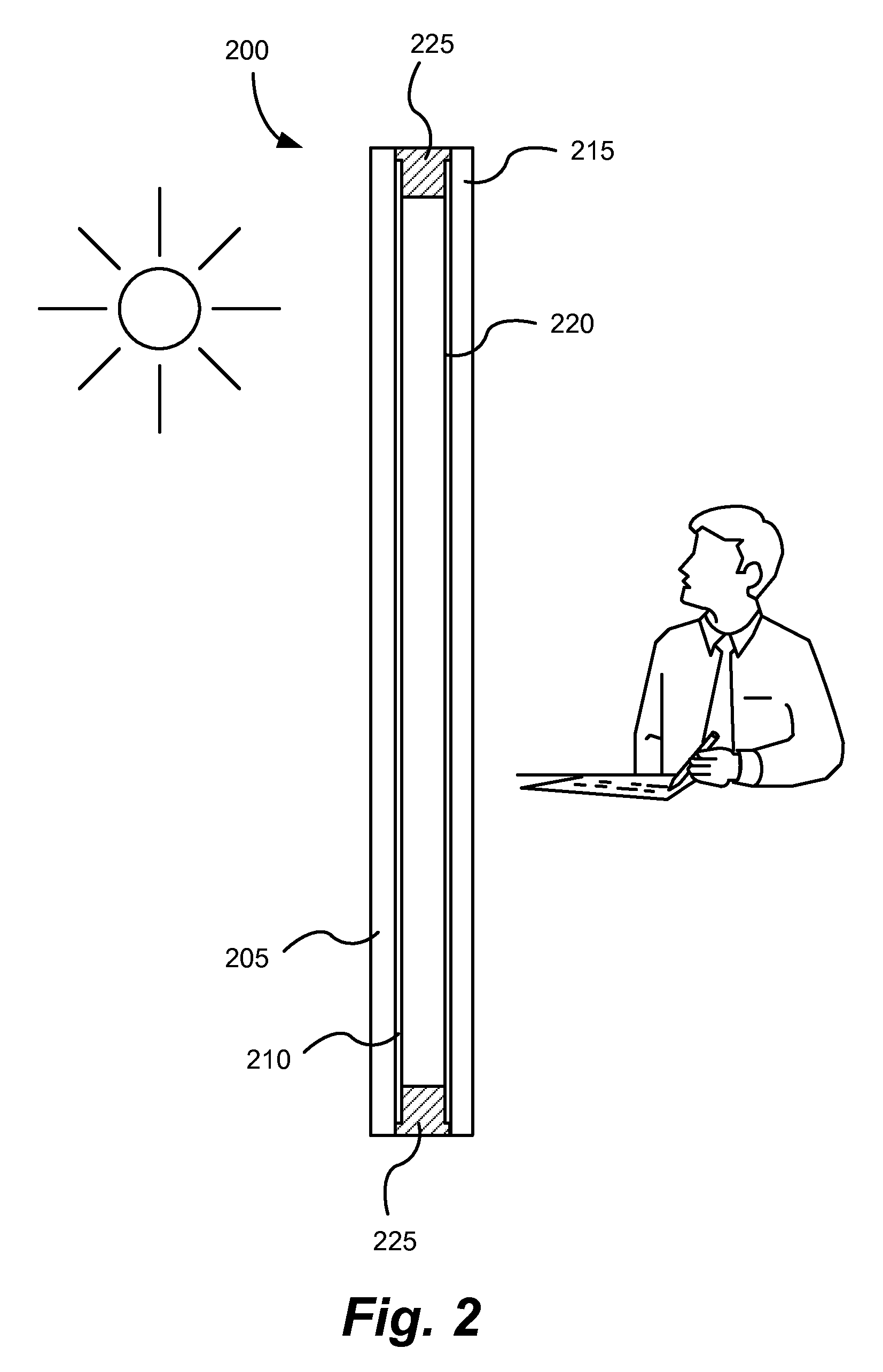
[0026]Herein are described window units, for example IGU's, that have at least two panes, each pane having an electrochromic device thereon. For example, when a window unit has two panes, each with two optical states, then the window unit can have four optical states. Window units described herein allow the window user a greater choice of how much light is transmitted through the electrochromic window, that is, the multi-pane IGU concept allows a gradation of transmission rather than a simple “on or off” conventional two-state window. A secondary benefit is the improvement in defectivity due to non-aligned optical defects, even for two-state windows. The inventors have discovered that by using two or more window panes, each with its own electrochromic device, registered in a window unit, that is, one in front of the other, visual defects in any of the individual devices are negated by virtue of the extremely small likelihood that any of the visual defects will align perfectly and th...


PUM

PropertyMeasurementUnit
transmittanceaaaaaaaaaa

Abstract

Window units, for example insulating glass units (IGU's), that have at least two panes, each pane having an electrochromic device thereon, are described. Two optical state devices on each pane of a dual-pane window unit provide window units having four optical states. Window units described allow the end user a greater choice of how much light is transmitted through the electrochromic window. Also, by using two or more window panes, each with its own electrochromic device, registered in a window unit, visual defects in any of the individual devices are negated by virtue of the extremely small likelihood that any of the visual defects will align perfectly and thus be observable to the user.

Description

FIELD OF INVENTION[0001]The invention relates generally to electrochromic devices, more particularly electrochromic windows.BACKGROUND[0002]Electrochromism is a phenomenon in which a material exhibits a reversible electrochemically-mediated change in an optical property when placed in a different electronic state, typically by being subjected to a voltage change. The optical property is typically one or more of color, transmittance, absorbance, and reflectance. One well known electrochromic material, for example, is tungsten oxide (WO3). Tungsten oxide is a cathodic electrochromic material in which a coloration transition, transparent to blue, occurs by electrochemical reduction.[0003]While electrochromism was discovered in the 1960's, electrochromic devices still unfortunately suffer various problems and have not begun to realize their full commercial potential. Electrochromic materials may be incorporated into, for example, windows and mirrors. The color, transmittance, absorbance...

Claims


Application Information

Patent Timeline
18 Sep 2012
Publication
US8270059B2
IPC
G02F1/153; G02F1/1523
CPC
C03C17/34; C03C17/36; C03C17/3657; C03C17/3681; H05B3/86; G02F1/1523; E06B9/24; G02F1/153
Inventors
FRIEDMAN, ROBIN; KAILASAM, SRIDHAR