Fluid handling structure, a lithographic apparatus and a device manufacturing method

a technology of lithographic apparatus and liquid handling, applied in the direction of flexible pipes, gas/liquid distribution and storage, printers, etc., can solve the problems of increasing defectivity, less readily dissolving of gas bubbles, and contaminated atmosphere, so as to suppress the evaporation of liquid, reduce the defectivity of gas bubbles in the immersion space, and dissolve more readily

Active Publication Date: 2013-03-21
ASML NETHERLANDS BV
View PDF6 Cites 17 Cited by
  • Summary
  • Abstract
  • Description
  • Claims
  • Application Information

AI Technical Summary

Benefits of technology

[0007]A fluid handling structure may comprise a gas supply opening that supplies gas. The gas may have a special physical property, for example it may provide an atmosphere around a liquid meniscus which may enable gas bubbles formed in the immersion liquid, such as water, to dissolve more readily than atmospheric gas (e.g., air). Image defectivity caused by gas bubbles in the immersion space may be reduced. The atmosphere around the meniscus may suppress evaporation of liquid from the meniscus by having a high level of humidity. The gas external to the fluid handling structure may have a special physical property. The external gas, such as air, may form an atmosphere with a substantially constant refractive index, which facilitates accurate positioning and measurement. If the two gases mix by a small quantity escaping to the other, the desired performance of the respective atmosphere is reduced. The respective atmosphere is contaminated. For example, gas bubbles may less readily dissolve in the immersion space, increasing defectivity and decreasing yield. If the external atmosphere has a non-uniform refractive index, this may interfere undesirably with performance of an interferometer, or other optical component, outside the fluid handling structure.
[0008]It is desirable, for example, to provide a lithographic apparatus in which mixing of gas from and external to the fluid handling structure is at least partly reduced or prevented.
[0010]According to an aspect, there is provided a device manufacturing method, comprising: projecting a patterned beam of radiation through an immersion liquid confined to a space between a projection system and a substrate by a fluid handling structure; providing gas through at least one gas supply opening to a position adjacent a meniscus of the immersion liquid; recovering gas through at least one fluid recovery radially outward of the at least one gas supply opening; and damping the movement of gas from the at least one fluid recovery opening to radially outward of the fluid handling structure by a damper surface extending at least 0.5 mm radially outwards from the at least one fluid recovery opening along the undersurface of the fluid handling structure.
[0012]According to an aspect, there is provided a device manufacturing method, comprising: projecting a patterned beam of radiation through an immersion liquid confined to a space between a projection system and a substrate by a fluid handling structure; providing gas through at least one gas supply opening to a position adjacent a meniscus of the immersion liquid; recovering gas through at least one fluid recovery opening radially outward of the at least one gas supply opening; and damping the movement of gas from the at least one fluid recovery opening to radially outward of the fluid handling structure by a damper surface extending radially outwards from the at least one fluid recovery opening along the undersurface of the fluid handling structure, wherein the separation between the at least one fluid recovery opening and an outer radial edge of the undersurface is at least five times the distance between the fluid handling structure and a facing surface facing the projection system.
[0014]According to an aspect, there is provided a fluid handling structure for a lithographic apparatus comprising a projection system and a substrate table configured to support a substrate, the fluid handling structure configured to confine immersion liquid to a space between the projection system and a facing surface, the fluid handling structure having an undersurface region external and surrounding the space. The fluid handling structure has: at least one gas supply opening outward of the space, the gas supply opening configured to supply a gas flow between the undersurface and facing surface; and a blocking damper between the gas supply opening and an outer edge of the undersurface of the fluid handling structure, the blocking damper configured to substantially block a radial gas flow from the gas supply opening to an atmosphere external the fluid handling structure, or to substantially block a radial gas flow from the external atmosphere to the gas supply opening, or both, so as to substantially prevent mixing between the gas from the gas supply opening and the external atmosphere.
[0015]According to an aspect, there is provided a fluid handling structure that has, at a boundary of a space configured to contain immersion fluid to a region external to the fluid handling structure: at least one gas supply opening radially outward of the space; at least one fluid recovery opening radially outward of the at least one gas supply opening; an outer damper surface extending radially outwards from the at least one fluid recovery opening along an undersurface of the fluid handling structure so as to restrict gas flow from the at least one gas recovery opening to an outer radial edge of the undersurface of the fluid handling structure; and an inner damper surface extending radially between the at least one gas supply opening and the at least one fluid recovery opening along the undersurface of the fluid handling structure so as to restrict gas flow from the at least one fluid recovery opening to the at least one gas supply opening, wherein the inner damper surface and the outer damper surface restrict the gas flows approximately equally.

Problems solved by technology

The respective atmosphere is contaminated.
For example, gas bubbles may less readily dissolve in the immersion space, increasing defectivity and decreasing yield.
If the external atmosphere has a non-uniform refractive index, this may interfere undesirably with performance of an interferometer, or other optical component, outside the fluid handling structure.

Method used


Image

  • Fluid handling structure, a lithographic apparatus and a device manufacturing method
  • Fluid handling structure, a lithographic apparatus and a device manufacturing method
  • Fluid handling structure, a lithographic apparatus and a device manufacturing method

Examples


Embodiment Construction

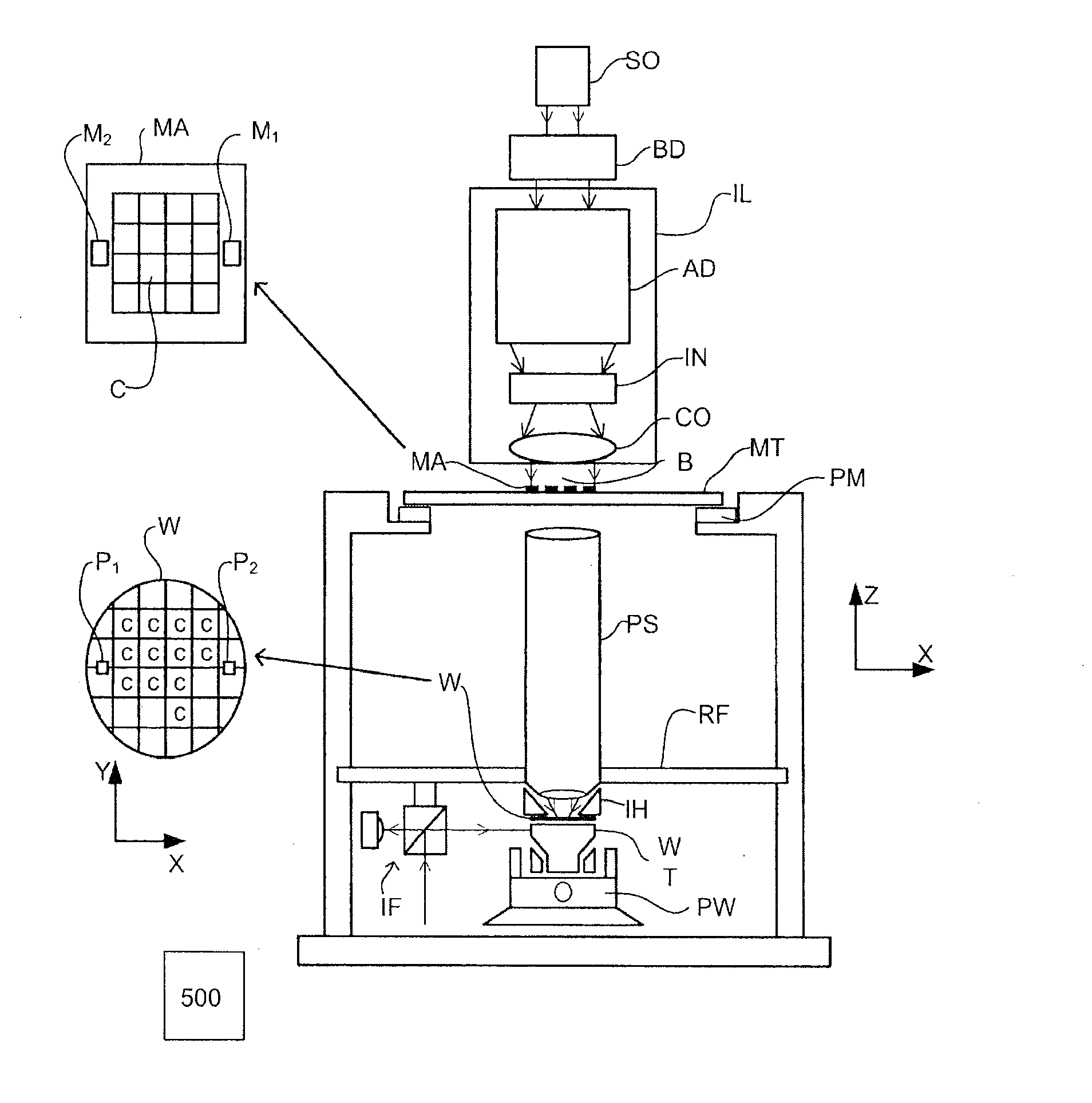
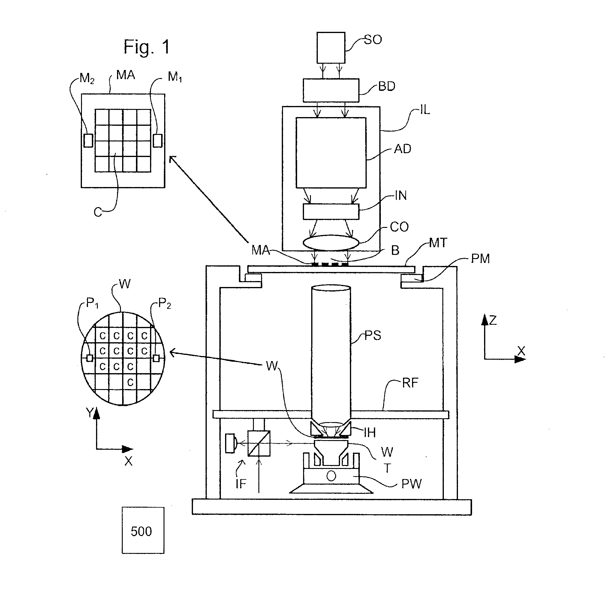
[0026]FIG. 1 schematically depicts a lithographic apparatus according to one embodiment of the invention. The apparatus comprises:[0027]an illumination system (illuminator) IL configured to condition a radiation beam B (e.g. UV radiation or DUV radiation);[0028]a support structure (e.g. a mask table) MT constructed to support a patterning device (e.g. a mask) MA and connected to a first positioner PM configured to accurately position the patterning device MA in accordance with certain parameters;[0029]a support table, e.g. a sensor table to support one or more sensors or a substrate table WT constructed to hold a substrate (e.g. a resist-coated substrate) W, connected to a second positioner PW configured to accurately position the surface of the table, for example of a substrate W, in accordance with certain parameters; and[0030]a projection system (e.g. a refractive projection lens system) PS configured to project a pattern imparted to the radiation beam B by patterning device MA o...


PUM


Abstract

A fluid handling structure for a lithographic apparatus has, at a boundary of a space configured to contain immersion fluid to a region external to the fluid handling structure, a gas supply opening radially outward of the space, a fluid recovery opening radially outward of the gas supply opening, and a damper surface extending at least 0.5 mm radially outwards from the fluid recovery opening along the undersurface of the fluid handling structure.

Description

[0001]This application claims priority and benefit under 35 U.S.C. §119(e) to U.S. Provisional Patent Application No. 61 / 535,066, filed on Sep. 15, 2011. The content of that application is incorporated herein in its entirety by reference.FIELD[0002]The present invention relates to a fluid handling structure, a lithographic apparatus and a method for manufacturing a device using a lithographic apparatus.BACKGROUND[0003]A lithographic apparatus is a machine that applies a desired pattern onto a substrate, usually onto a target portion of the substrate. A lithographic apparatus can be used, for example, in the manufacture of integrated circuits (ICs). In that instance, a patterning device, which is alternatively referred to as a mask or a reticle, may be used to generate a circuit pattern to be formed on an individual layer of the IC. This pattern can be transferred onto a target portion (e.g. comprising part of, one, or several dies) on a substrate (e.g. a silicon wafer). Transfer of ...

Claims


Application Information

Patent Timeline
Patent Type & Authority Applications(United States)
IPC IPC(8): G03B27/52F17D3/00
CPCG03F7/70341Y10T137/8593
Inventor BESSEMS, DAVIDROPS, CORNELIUS MARIA
Owner ASML NETHERLANDS BV
Why Eureka
Try Eureka