
Dynamic dithering for video compression

a dynamic dithering and video compression technology, applied in the field of video processing techniques and devices, can solve the problems of blockage artifacts, loss of all the details of the input picture frame, and many adverse effects of quantization errors on the perception of the underlying video

Inactive Publication Date: 2012-09-18
APPLE INC
View PDF12 Cites 3 Cited by
  • Summary
  • Abstract
  • Description
  • Claims
  • Application Information

AI Technical Summary

Benefits of technology

The patent text describes a technique for reducing banding artifacts in video compression, which can be a problem in some cases. The technique involves using dithering to mask the effects of quantization errors, but there is a need for a dynamic method that can estimate the locations and amount of dithering needed to reduce the banding effects. The invention aims to improve the quality of video compression and reduce the impact of quantization errors on the perceived quality of the video.

Problems solved by technology

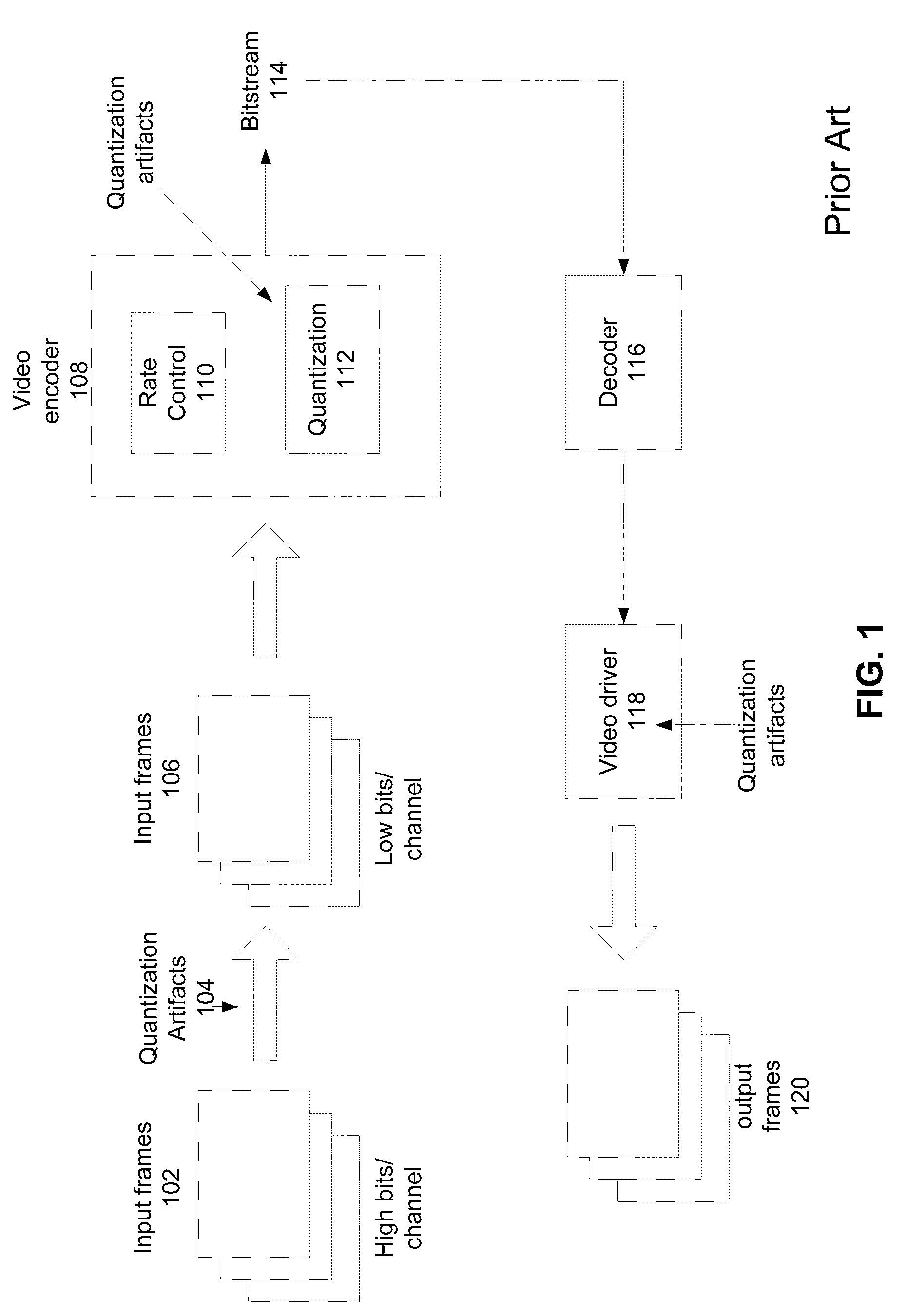
For video compression, quantization errors may have many adverse effects on the perception of the underlying video.
The block artifacts may be directly caused by block-based video compression schemes where pixel blocks are used to encode video.
If the quantization is too strong (e.g., when the very low bitrates force the encoder to compress the video too deep), only a uniform color-flat block may be locally visible and thus lose all the details from the input picture frame.
However, in other situations, the provider may not.
This banding effect may be due to limitations in the block-based coding models in existing standards such as MPEG-2 or H.264.
Having a color gradient whose slope is finer than the minimum quantization step allowed may most likely to cause visible artifacts on the final picture frames.
Additionally, the amount of noise added in dithering may depend on many factors.

Method used


Image

  • Dynamic dithering for video compression
  • Dynamic dithering for video compression
  • Dynamic dithering for video compression

Examples


Embodiment Construction

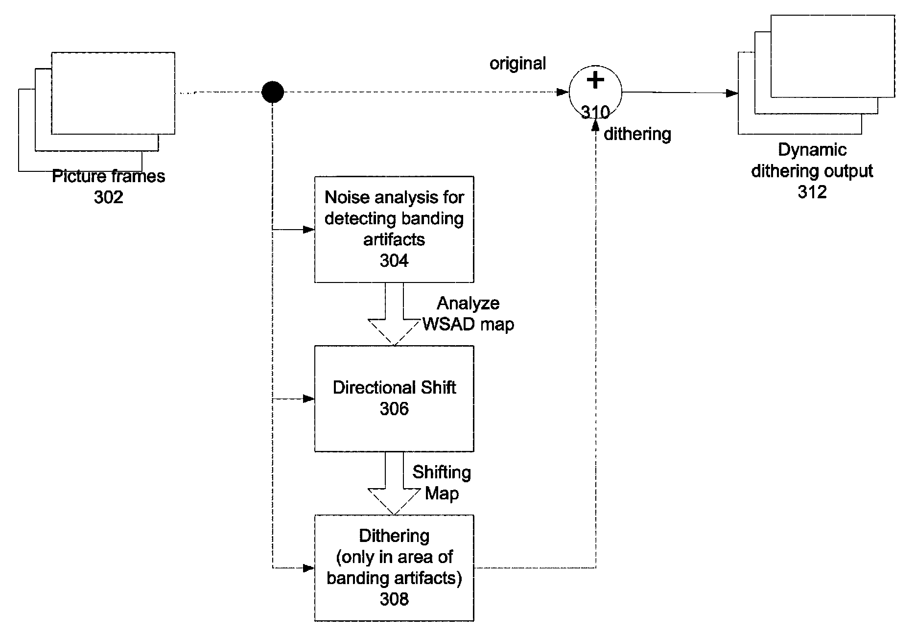
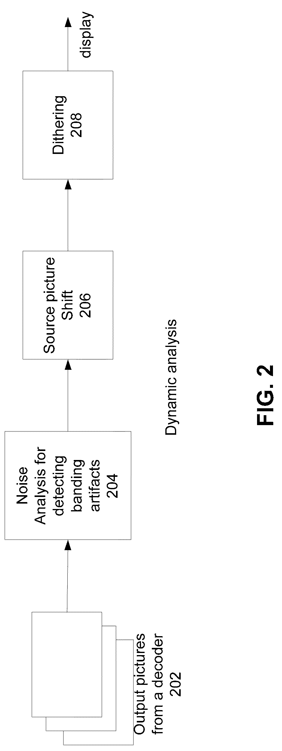
[0026]Embodiments of the present invention may provide a method and device for dithering video from a decoder. The method and device provide: selecting a segment of video frames from the video; computing a noise map for the segment of the video, the noise map computed from differences among pixels selected from spatially-distributed sampling patterns in the segment; determining contours of quantization artifacts within the video frame based on the noise map and a histogram of pixel values in the video frame; computing a gradient measurement of pixel values along the contours; identifying regions along the contours of quantization artifacts to apply dithering based on the noise map and the gradient measurement; determining a dithering strength based on the noise map and the gradient measurement; and applying dithering noise to the identified regions at the determined dithering strength.

[0027]Embodiments of the present invention may provide a method and device for dithering video from...


PUM


Abstract

A method and device for dithering video from a decoder. The method and device provide: selecting a segment of video frames from the video; computing a noise map for the segment of the video, the noise map computed from differences among pixels selected from spatially-distributed sampling patterns in the segment; determining contours of quantization artifacts within the video frame based on the noise map and a histogram of pixel values in the video frame; computing a gradient measurement of pixel values along the contours; identifying regions along the contours of quantization artifacts to apply dithering based on the noise map and the gradient measurement; determining a dithering strength based on the noise map and the gradient measurement; and applying dithering noise to the identified regions at the determined dithering strength.

Description

CROSS-REFERENCE TO RELATED APPLICATIONS[0001]This application claims priority to U.S. Provisional Patent Application No. 61 / 163,658, filed Mar. 26, 2009, entitled “Dynamic Dithering For Video Compression,” which is herein incorporated by reference in its entirety.FIELD OF THE INVENTION[0002]The present invention is generally directed to video processing techniques and devices. In particular, the present invention is directed to dithering for reducing banding or quantization artifacts in video images.BACKGROUND INFORMATION[0003]Quantization is widely used in video coding or video compression. Quantization is a non-linear process that allows reducing the amount of bits needed for encoding a specific information. In general, quantization is a lossy process. Many methods exist for reducing quantization errors in a quantized signal.[0004]For video compression, quantization errors may have many adverse effects on the perception of the underlying video. Some of the effects may be immediate...

Claims


Application Information

Patent Timeline
Patent Type & Authority Patents(United States)
IPC IPC(8): H04N7/12G06K9/40
CPCH04N19/124H04N19/136H04N19/90H04N19/86H04N19/154
Inventor FILIPPINI, GIANLUCAWU, HSI-JUNGNORMILE, JAMES OLIVERSHI, XIAOJINZHOU, XIAOSONGHRISTODORESCU, IONUT
Owner APPLE INC
Learn More