Head restraint device having a support member with back and shoulder portions

a head restraint and support member technology, applied in the direction of pedestrian/occupant safety arrangements, sport apparatus, vehicular safety arrangements, etc., can solve the problems of unfavorable head and neck movement of drivers, serious injuries including death, and elevated tension forces in the spine and neck, so as to improve the ability of the restraint device

Inactive Publication Date: 2012-09-25
SIMPSON PERFORMANCE PRODUCTS
View PDF47 Cites 13 Cited by
  • Summary
  • Abstract
  • Description
  • Claims
  • Application Information

AI Technical Summary

Benefits of technology

[0019]In an embodiment of the present invention, the restraint device controls a driver's head and neck in the event of a vehicle collision. The restraint device includes a support member having a back portion and shoulder portions that extend at least partially the over the shoulders of the driver; at least one tether that is attached to the support member and is adapted for being attached to a helmet; and at least one anchor strap that is attached to the support member and is adapted for being attached to a vehicle's seat belt assembly. The restraint device cooperates with the seat belt assembly such that the seat belt assembly serves as an anchor to control movement of the driver's head during a vehicle collision event. Also, the vehicle's shoulder belts react against the shoulder portions which improve the restraint device's ability to resist forward and downward movement of the driver's head that may occur during a collision event. Optionally, the tethers are angled inwards and upwards from the support member to the helmet. Also optionally, the anchor strap is attached to the coupling means of the seat belt assembly such that the driver is freed from being secured to the vehicle by releasing the seat belt assembly coupling means. As a further option, the restraint device may further include another anchor strap which anchors the device to the driver's body, such as for example to the driver's torso and / or legs.

Problems solved by technology

Although standard seat belt assemblies are effective in constraining the torso of the driver to the seat assembly during a collision event, it does not restrain the driver's head or neck.
Rear impacts may also cause undesirable movement of the driver's head and neck.
Further, side impacts may cause the driver's head and neck to tilt sideways, resulting in significant and unequal loading conditions wherein one side of the neck may bear the vast majority of the loading as compared to the opposed side.
In the aforementioned impact scenarios, uncontrolled movement of the driver's head and neck, and resulting excessive loading thereto, has resulted in serious injury including death.
Additionally, downward rotation of the driver's head may cause elevated tension forces to occur in the spine and neck.
Where the tension forces are sufficiently high, a basilar skull fracture may occur, a condition in which the base of the skull cracks from the stem.
However, this approach is problematic in that after the initial impact, the inflated airbag would block the driver's field of vision.
Another problem is that the air bags would have to deploy much more quickly and with more explosive force than it would have to with conventional vehicles, due to the greater speeds at which high-performance vehicles are operated.
The Hans Device® is configured principally for frontal collisions, being less effective in angular-frontal and side impacts.
Another disadvantage of the Hans Device® is that the structure of the yoke may inadvertently cause the device to become a safety hazard by impeding the driver from quickly exiting the vehicle.
However, the stiff and bulky yoke of the Hans Device® may make it more difficult to move and fit through the driver-side window frame.
Consequently, valuable time in removing the driver from a dangerous crash site and to treat the driver may be lost.
This need to quickly exit the vehicle is particularly critical when the driver and / or vehicle are on fire or when the driver is seriously injured.
A further disadvantage of the Hans Device® is that the driver's seat must be modified in order to accommodate the bulky yoke.
Accordingly, the device cannot be used in a vehicle until costly modification to the vehicle's seat assembly has been made.
Still another disadvantage of the Hans Device® is that some drivers consider the bulky yoke as being uncomfortable and that the yoke restricts their mobility when operating the vehicle.
Moreover, some drivers have also noted that yoke limits their peripheral view.
These limitations of the Hans Device® may potentially lead to driver error.

Method used


Image

  • Head restraint device having a support member with back and shoulder portions
  • Head restraint device having a support member with back and shoulder portions
  • Head restraint device having a support member with back and shoulder portions

Examples


Embodiment Construction

[0035]The present invention will now be described more fully hereinafter with reference to the accompanying drawings in which preferred embodiments of the invention are shown. This invention may, however, be embodied in many different forms and should not be considered as limited to the embodiments set forth herein. These exemplary embodiments are provided so that this disclosure will be both thorough and complete, and will fully convey the scope of the invention to those skilled in the art. Like reference numbers refer to like elements throughout the various FIGS.

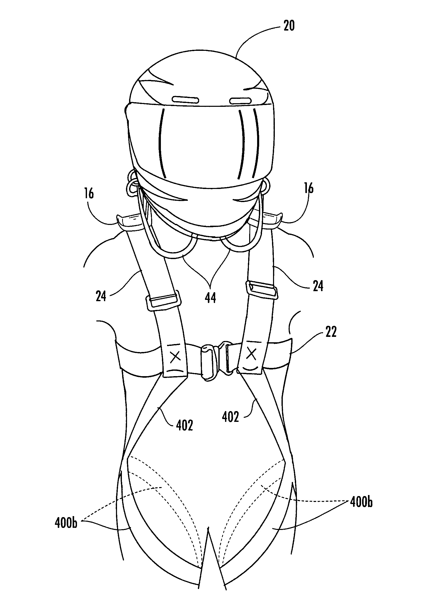
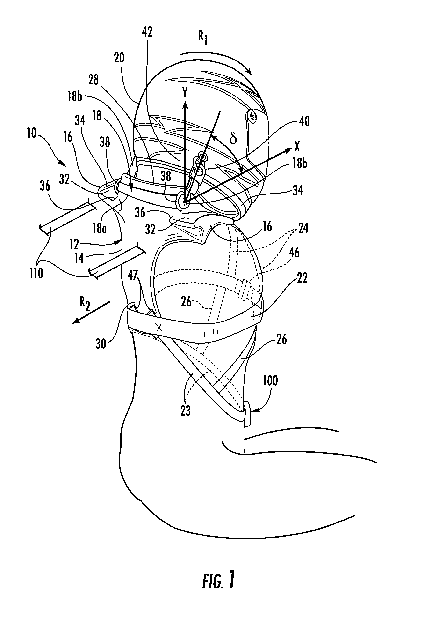
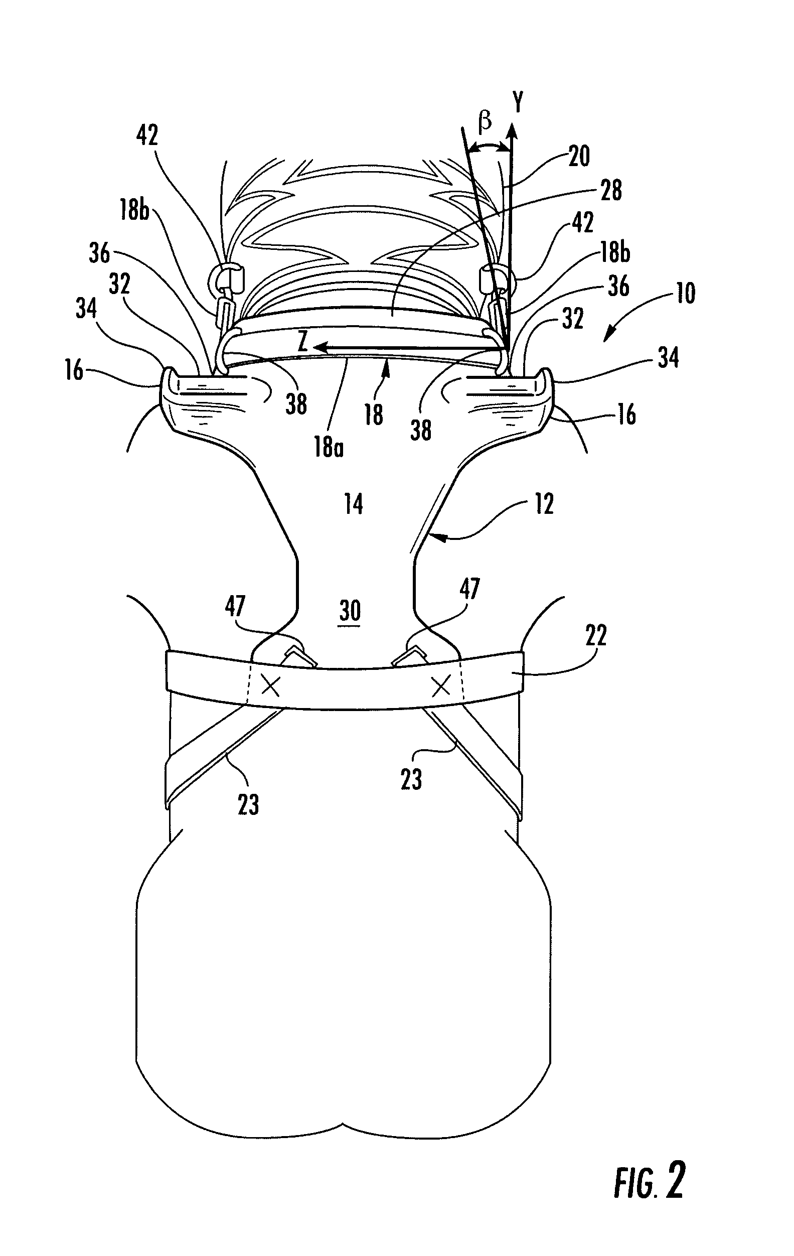
[0036]The present invention describes a restraint device that provides protection to a driver's head and neck beyond that offered by just a vehicle's seat belt assembly. During a high-performance vehicle collision, standard 5 or 6 point seat belt assemblies will limit forward advancement of a driver's torso from the vehicle's seat assembly. However, the driver's head, unrestrained, is free to continue forward and caused to...


PUM


Abstract

A restraint device for controlling the head of a driver during a high-performance vehicle collision. The device includes a support member having a back portion and shoulder portions that extend at least partially over the shoulders of the driver; a tether for attaching the support member to the driver's helmet; and at least one anchor strap attached at one end to the support member and at the other end to the vehicle's seat belt assembly, driver's truck, and/or driver's legs, which serves to anchor the device and oppose forward and rearward movement of the driver's head during a collision event, reducing the likelihood of injury. The shoulder portions are configured to engage the vehicle's shoulder belts, which improves the restraint device's ability to resist forward movement and downward rotation of the driver's head that is caused by a collision event.

Description

CROSS REFERENCE TO RELATED APPLICATIONS[0001]This is a continuation-in part of application Ser. No. 11 / 131,782, filed May 17, 2005 now U.S. Pat. No. 7,765,623 B2, which is a continuation-in-part of application Ser. No. 10 / 728,003, filed Dec. 3, 2003, now U.S. Pat. No. 6,931,669 B2, and claims the benefit of U.S. Provisional Application No. 60 / 797,921, filed May 5, 2006, each of which is hereby incorporated by reference.BACKGROUND OF THE INVENTION[0002]1. Field of the Invention[0003]The present invention relates to the field of safety devices worn by a driver when operating a high-performance vehicle. More specifically, the present invention relates to a restraint device that controls movement of, and reduces forces applied to, a driver's head, neck and spine when the driver is subjected to high deceleration forces, such as those forces that may occur during a collision event while operating a high-performance vehicle.[0004]2. Description of the Related Art[0005]Traditionally, driver...

Claims


Application Information

Patent Timeline
Patent Type & Authority Patents(United States)
IPC IPC(8): A42B7/00
CPCA42B3/0473B60R22/001B60R2021/0086
Inventor ASHLINE, TREVOR P.
Owner SIMPSON PERFORMANCE PRODUCTS
Why Eureka
Try Eureka