Attachment profile

a technology of attaching profile and stud wall, which is applied in the direction of shaping building parts, building components, structural elements, etc., can solve the problems of lack of intrinsic strength, which is sometimes needed for attaching stud walls, and questionable design can only be used in connection with linear stud walls, i.e., not in connection with round walls or other curved walls or wall sections, etc., and achieves the effect of easy implementation

Active Publication Date: 2012-10-02
PROTEKTORWERK FLORENZ MAISCH
View PDF15 Cites 7 Cited by
  • Summary
  • Abstract
  • Description
  • Claims
  • Application Information

AI Technical Summary

Benefits of technology

[0013]Proceeding from this problem, it is an object of the present invention to provide an improved attachment profile for a wall erected in dry mortarless construction, which fundamentally avoids the described disadvantages of the prior art and opens up further applications.

Problems solved by technology

The previously known attachment profile also relates to the problems of having to connect U-profiles to erect a stud wall produced in dry mortarless construction or a wall having to be connected to the floor and the ceiling of a structure and having to be braced and fastened predominantly in the horizontal direction of the situated attachment profile for this purpose.
In a design of this type, the problem exists of how the upper attachment profile, which is predominantly implemented as a U or L profile, is to be connected on one side to the vertically erected stud profiles and on the other side to the typically diagonally aligned roof truss, so that the stud wall erected in dry mortarless construction is reliably fixed in this way.
However, practice has shown that the design, because of the fastening tabs incorporated on both sides of the profile web, may lack the intrinsic strength which is sometimes needed for securing the stud walls.
Moreover, the questionable design could only be used in connection with linear stud walls, i.e., not in connection with round walls or other curved walls or wall sections, for example.

Method used


Image

  • Attachment profile
  • Attachment profile
  • Attachment profile

Examples


Embodiment Construction

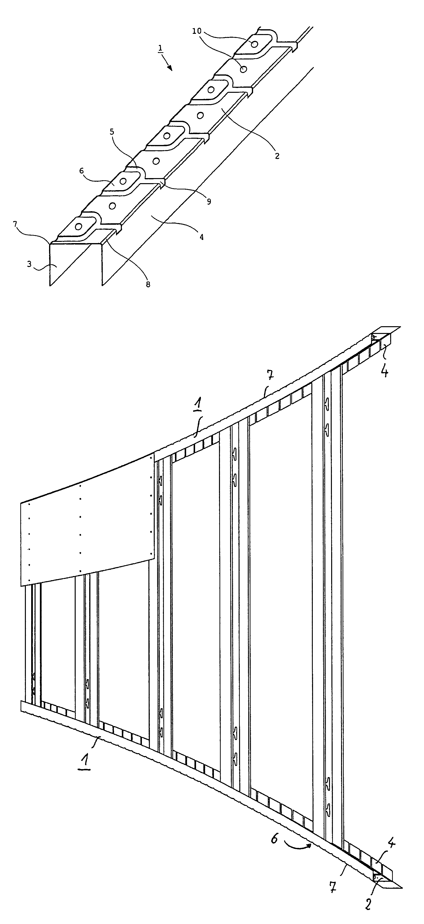
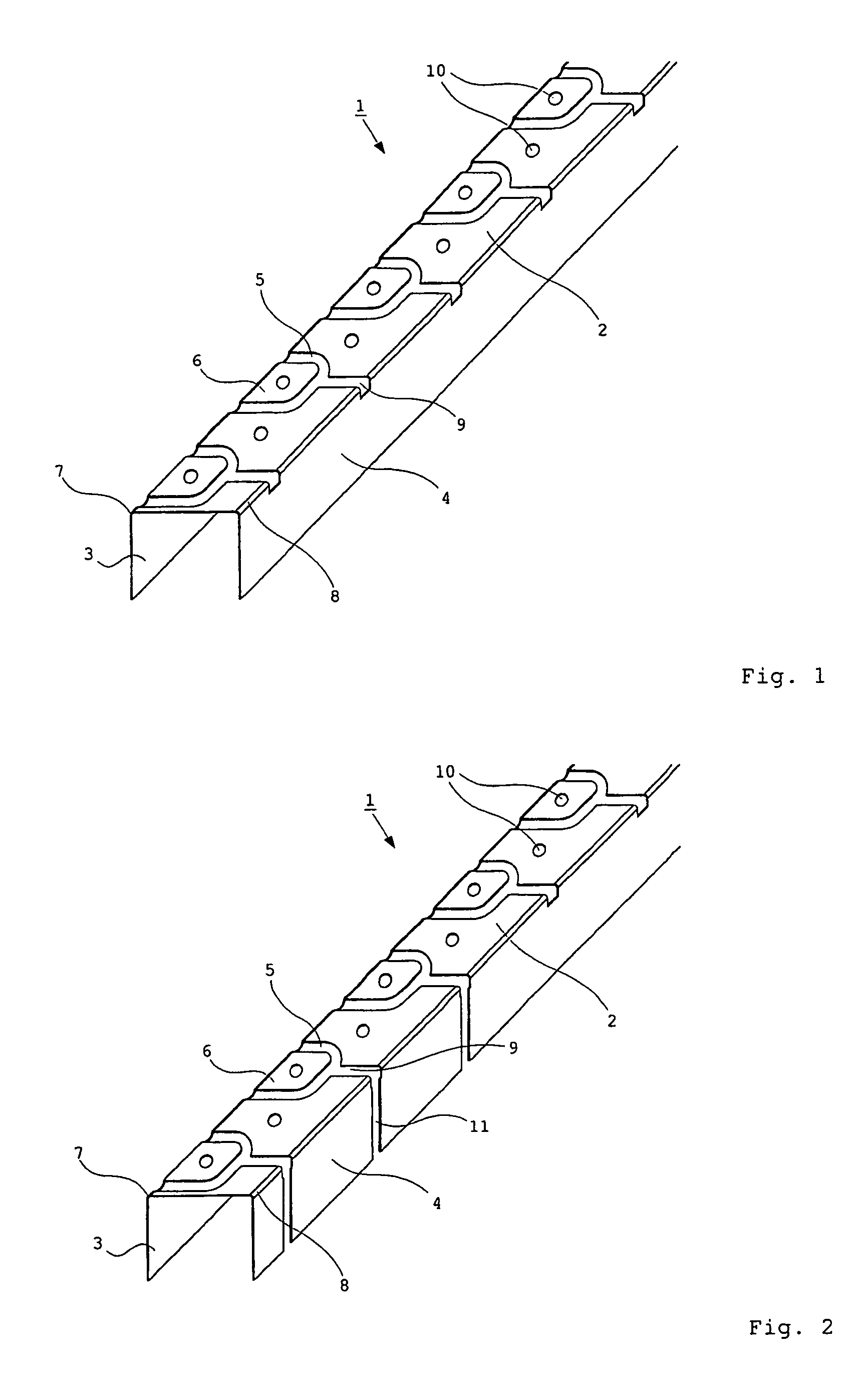
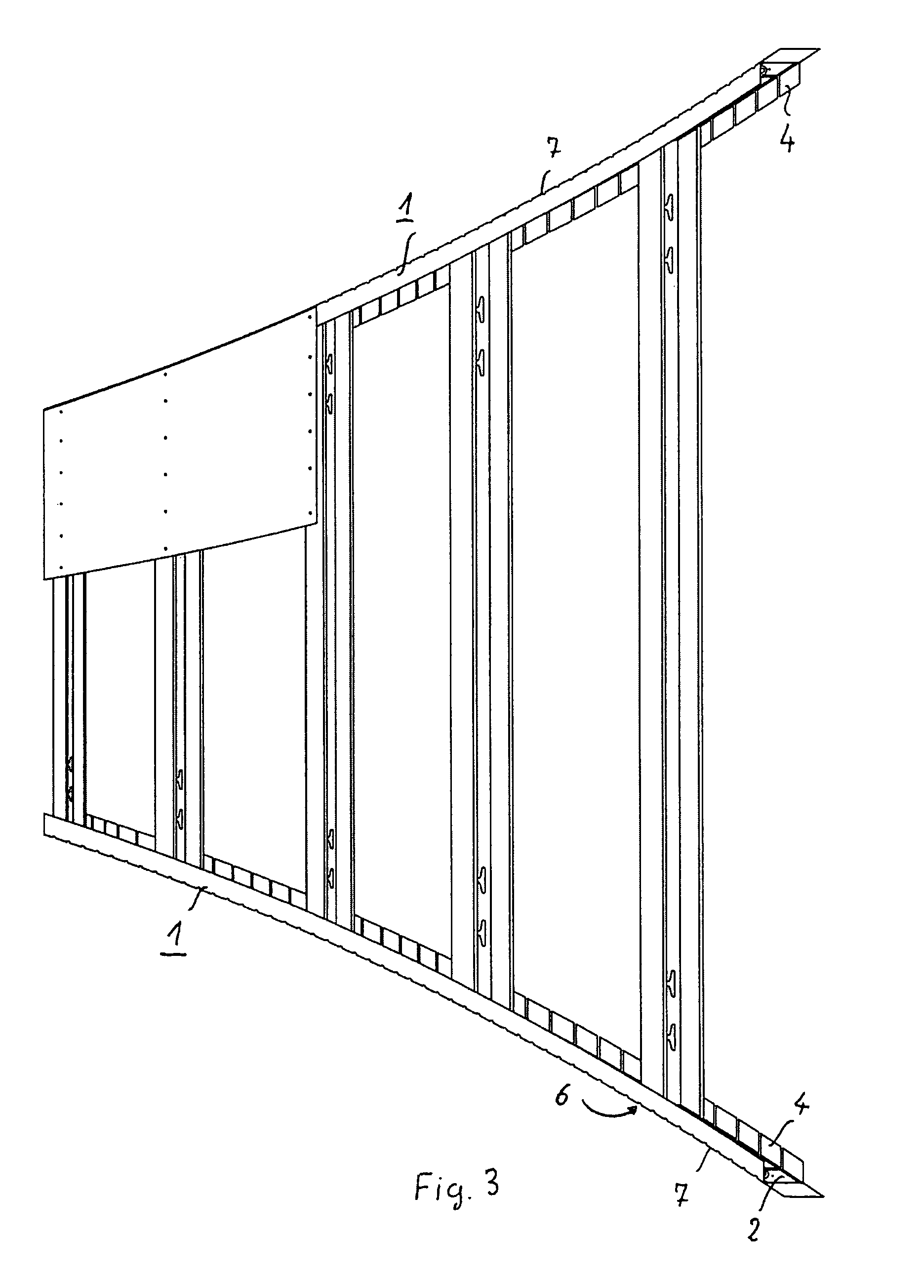
[0033]Referring now in detail to the drawings, FIG. 1 shows an attachment profile 1 in a perspective illustration, as is used to be connected in an approximately horizontal orientation to the studs, which are situated in an approximately vertical orientation, of a stud wall produced in dry mortarless construction on one side and two inclines (not shown in greater detail here) of a ceiling or roof structure on the other side.

[0034]Attachment profile 1 has an at least extensively U-shaped cross-section, which is formed by a profile web 2 and two side webs 3, 4, which are connected to one another by profile web 2. Fastening tabs 6 are cut out of profile web 2 by corresponding notches 5. Fastening tabs 6 are only situated on one side of attachment profile 1.

[0035]Fastening tabs 6 are thus all linked around the same one deflection edge 7, which is connected to one side web 3 and profile web 2. Notches 5 are supplemented with further cutouts 9 extending up to the opposing other deflection...


PUM


Abstract

In the construction of walls in balloon framing below roof pitches, the attachment profiles need to be suitable for different inclines and are to be connectable to the incline. For this purpose, the attachment profiles have fastening tabs on both sides, which may be bent into the particular required inclined attitude. The fastening tabs extend nearly over the entire profile web and are only linked on a deflection edge on one side on the attachment profile in the area of the profile web. In addition, the attachment profile can be used for the upper and lower fixing of the sub profiles of a stud or stud round wall.

Description

CROSS REFERENCE TO RELATED APPLICATIONS[0001]Applicant claims priority under 35 U.S.C. §119 of German Application No. 20 2009 004 731 filed on Apr. 23, 2009 and European Application No. 09009325 filed on Jul. 17, 2009.BACKGROUND OF THE INVENTION[0002]1. Field of the Invention[0003]The invention relates to an attachment profile for terminating a wall erected in balloon framing, in particular a knee wall or a round wall, which can be placed on the upper and / or lower front sides of the at least approximately vertically erected stud profiles of the wall. The attachment profile has two side webs, which are spaced apart from one another by the width of a profile web, and are connected to one another by the profile web, and combine to form a U-shape. The profile web is notched in such a manner that the fastening tabs are cut out of the profile web so as to be pivotable around the deflection edge, which connects the side web to the fastening web in each case.[0004]2. The Prior Art[0005]Such...

Claims


Application Information

Patent Timeline
Patent Type & Authority Patents(United States)
IPC IPC(8): E04B2/00E04C3/00
CPCE04B2/7453E04B2/7457E04B2/789E04B2/82E04B2/825E04B7/045E04B2002/7481
Inventor WAIBEL, MARTIN
Owner PROTEKTORWERK FLORENZ MAISCH
Why Eureka
Try Eureka