
Strain monitoring system and apparatus

a monitoring system and a technology of a monitoring system, applied in the direction of osteosynthesis devices, applications, instruments, etc., can solve the problems of difficult monitoring of the efficacy of the fusion protocol by the physician, preventing patients from enjoying ordinary daily activities, and unable to determine the onset of spinal fusion after lumbar surgery

Active Publication Date: 2012-10-02
ST JUDE MEDICAL LUXEMBOURG HLDG II S A R L SJM LUX II
View PDF9 Cites 79 Cited by
  • Summary
  • Abstract
  • Description
  • Claims
  • Application Information

AI Technical Summary

Benefits of technology

"This patent is about a device that can sense strain on an implant in a person's body. The device has a sensor that is attached to the implant and it has a special circuit that can be connected to an external source of energy. When the implant is moved or subjected to a force, the sensor's circuit causes the frequency of the sensor to change. This change in frequency is used to determine the strain on the implant. Overall, this device allows for better monitoring and control of the implant's movement and can help improve the overall success of the implant."

Problems solved by technology

All of these different conditions can cause back and leg pain, which can result in debilitation and prevents the patient from enjoying ordinary daily activities.
One difficulty is that the biomechanical properties of a stable spinal fusion typically precedes the radiographic appearance of a solid fusion by at least eight weeks, which makes it difficult for a physician to monitor the efficacy of the fusion protocol.
Presently, the onset of spinal fusion after lumbar surgery continues to be difficult to determine, and, even though the implant provides internal fixation in a much shorter period of time, patients are frequently required to wear the brace for extended periods of time with the resulting detrimental effects to the patient's musculature.

Method used


Image

  • Strain monitoring system and apparatus
  • Strain monitoring system and apparatus
  • Strain monitoring system and apparatus

Examples


Embodiment Construction

[0032]The present invention can be understood more readily by reference to the following detailed description, examples, drawing, and claims, and their previous and following description. However, before the present devices, systems, and / or methods are disclosed and described, it is to be understood that this invention is not limited to the specific devices, systems, and / or methods disclosed unless otherwise specified, as such can, of course, vary. It is also to be understood that the terminology used herein is for the purpose of describing particular aspects only and is not intended to be limiting.

[0033]The following description of the invention is provided as an enabling teaching of the invention in its best, currently known embodiment. To this end, those skilled in the relevant art will recognize and appreciate that many changes can be made to the various aspects of the invention described herein, while still obtaining the beneficial results of the present invention. It will also...


PUM


Abstract

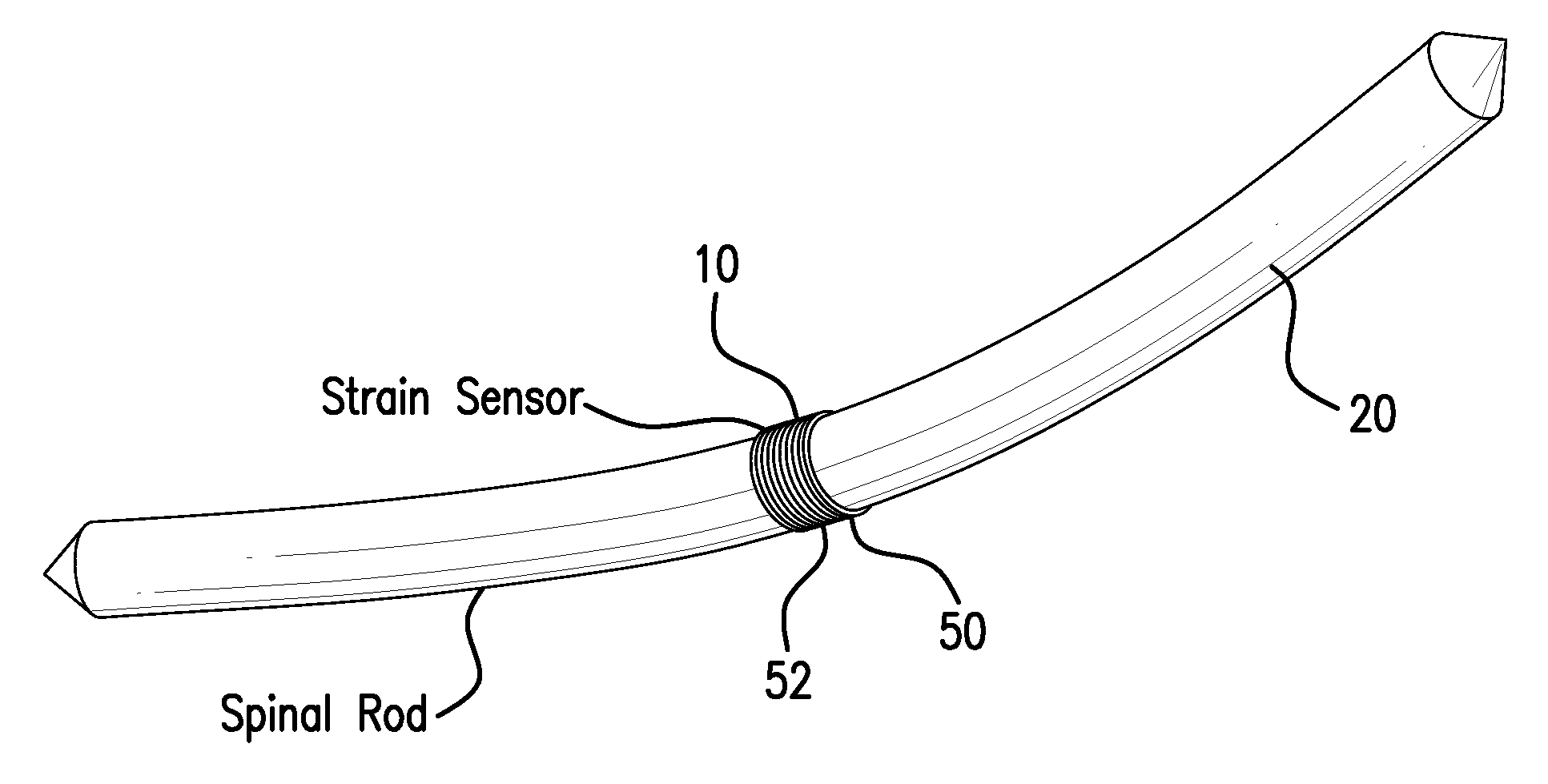
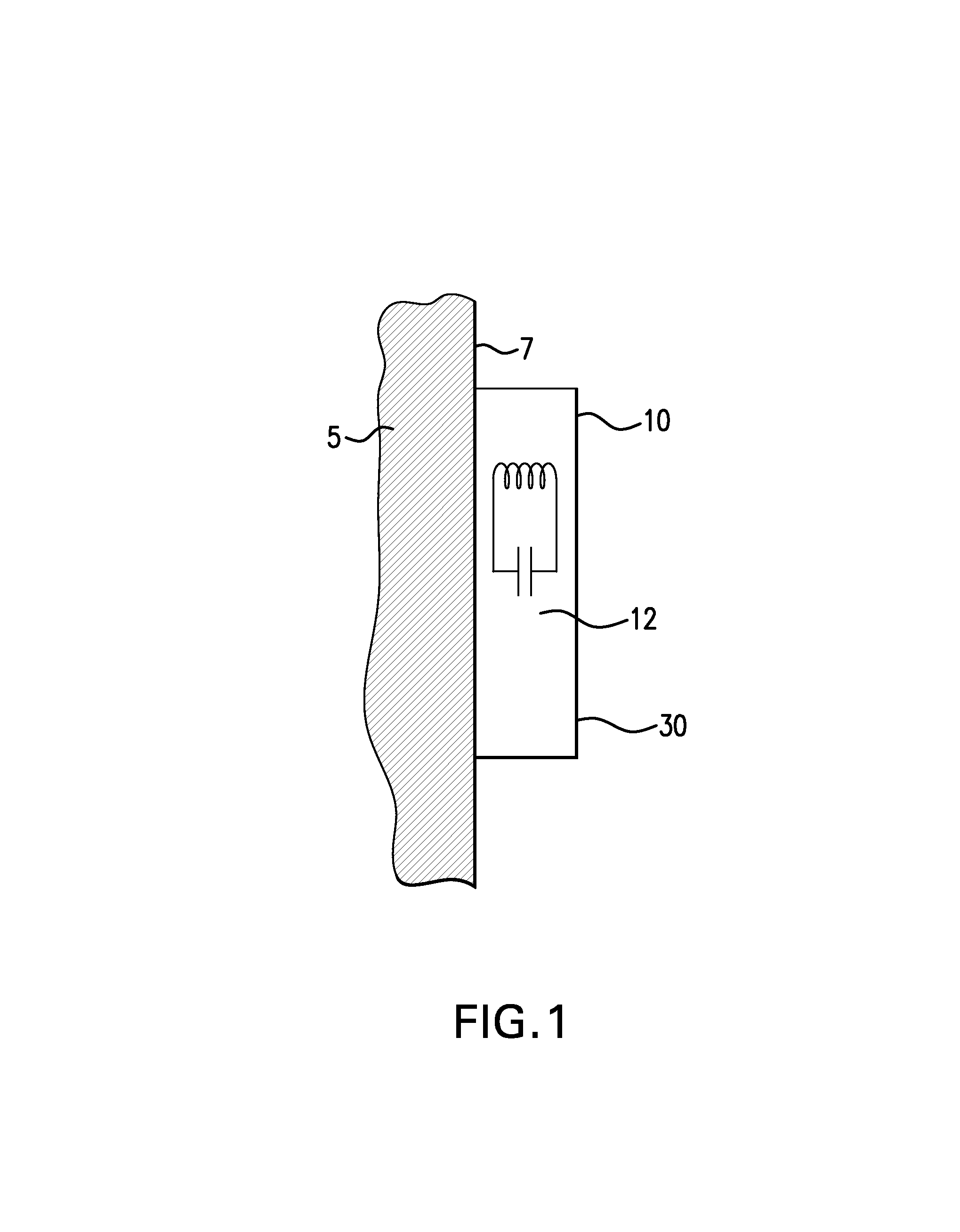
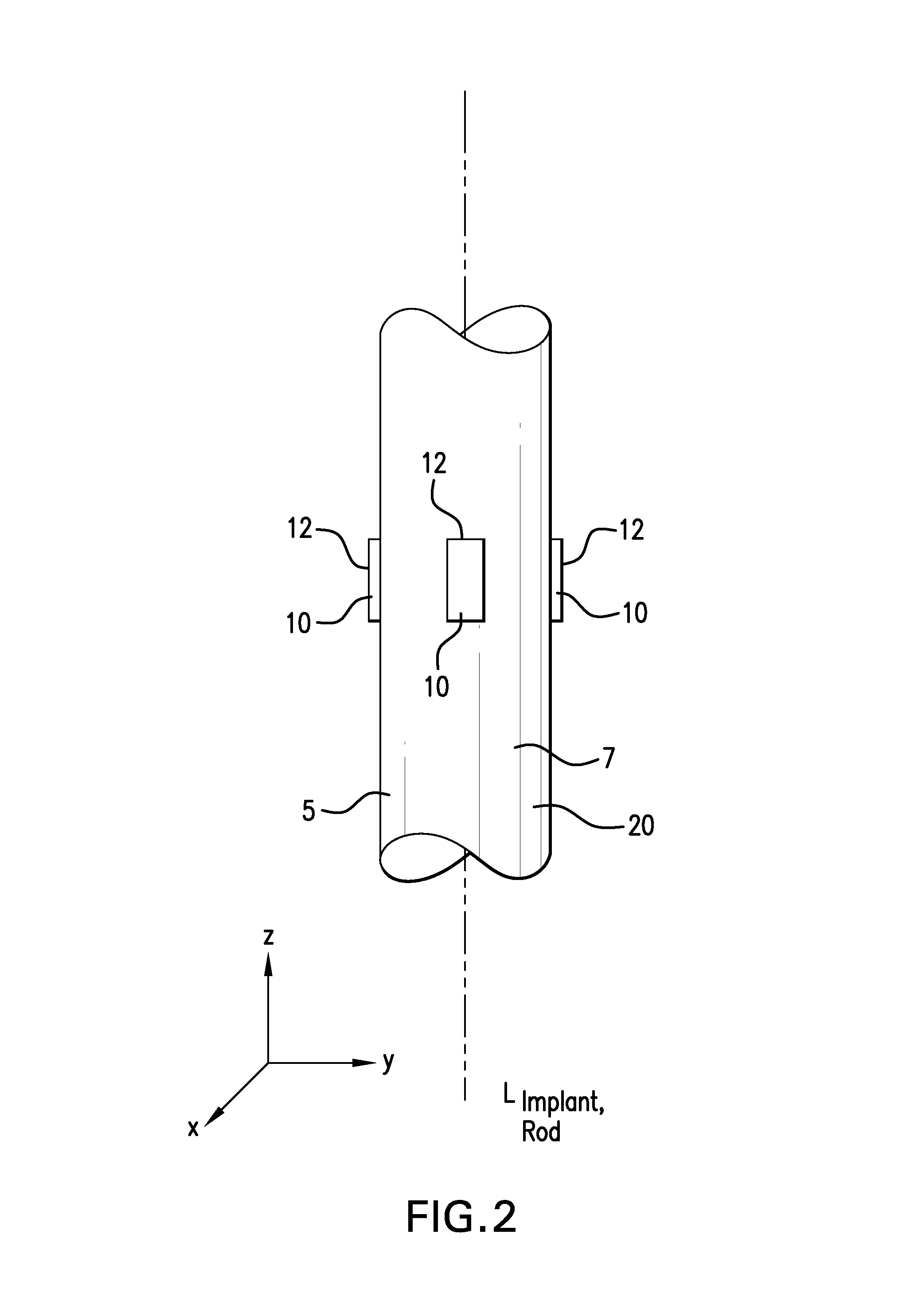
This application relates to an apparatus and system for sensing strain on a portion of an implant positioned in a living being. In one aspect, the apparatus has at least one sensor assembly that can be mountable thereon a portion of the implant and that has a passive electrical resonant circuit that can be configured to be selectively electromagnetically coupled to an ex-vivo source of RF energy. Each sensor assembly, in response to the electromagnetic coupling, can be configured to generate an output signal characterized by a frequency that is dependent upon urged movement of a portion of the passive electrical resonant circuit and is indicative of strain applied thereon a portion of the respective sensor assembly.

Description

[0001]This application is a continuation-in-part of U.S. patent application Ser. No. 11 / 613,645, filed on Dec. 20, 2006 now U.S. Pat. No. 7,550,978, which is a continuation of U.S. patent application Ser. No. 11 / 105,294, filed on Apr. 13, 2005, now U.S. Pat. No. 7,245,117, which claims priority to U.S. Provisional Application No. 60 / 623,959, filed on Nov. 1, 2004. This application is also a continuation-in-part of U.S. patent application Ser. No. 11 / 717,967, filed on Mar. 14, 2007, now U.S. Pat. No. 7,466,120, which is a continuation-in-part of U.S. patent application Ser. No. 11 / 276,571, filed on Mar. 6, 2006, now U.S. Pat. No. 7,498,799 which is a continuation-in-part of U.S. patent application Ser. No. 11 / 105,294, filed on Apr. 13, 2005, now U.S. Pat. No. 7,245,117, which claims priority to U.S. Provisional Application No. 60 / 623,959, filed on Nov. 1, 2004. U.S. patent application Ser. No. 11 / 717,967 also claims priority to U.S. Provisional Application No. 60 / 782,313, filed on Ma...

Claims


Application Information

Patent Timeline
Patent Type & Authority Patents(United States)
IPC IPC(8): G01R27/02
CPCA61B5/0031A61B5/076A61B17/7002G01F15/066G01L1/14G01L9/0073H01Q7/00A61B5/686A61B5/1116A61B5/4504A61B2017/00221A61B2560/0219A61B2560/0223A61B2562/0261
Inventor KROH, JASONCROS, FLORENTCOURCIMAULT, CHRISTOPHE
Owner ST JUDE MEDICAL LUXEMBOURG HLDG II S A R L SJM LUX II
Learn More