Supercharge Your Innovation With Domain-Expert AI Agents!

Method for performing pattern matching and line thinning on an image

a pattern matching and image technology, applied in the field of image processing devices, image processing methods, and image forming devices, can solve the problems of blue at boundary parts of electrostatic latent images, and discontinuous oblique stripe in an imag

Inactive Publication Date: 2012-10-02
FUJIFILM BUSINESS INNOVATION CORP
View PDF7 Cites 3 Cited by
  • Summary
  • Abstract
  • Description
  • Claims
  • Application Information

AI Technical Summary

Benefits of technology

The solution effectively prevents oblique stripes from becoming discontinuous during line-thinning, maintains image quality, and reduces data processing load, allowing for rapid rasterization of larger volumes of data while achieving line-thinning similar to offset printing methods.

Problems solved by technology

An image forming device which employs an electrophotographic method sometimes causes a problem of blurring at boundary parts of electrostatic latent images due to characteristics of photosensitive materials.
However, in case of an oblique stripe image, an oblique stripe in the image becomes discontinuous by performing a line-thinning processing only one time.
Also, in case of employing the Hilditch thinning algorithm, there is a case that an oblique stripe in an image becomes discontinuous.

Method used


Image

  • Method for performing pattern matching and line thinning on an image
  • Method for performing pattern matching and line thinning on an image
  • Method for performing pattern matching and line thinning on an image

Examples


first exemplary embodiment

A. First Exemplary Embodiment

[0043]A-1. Structure

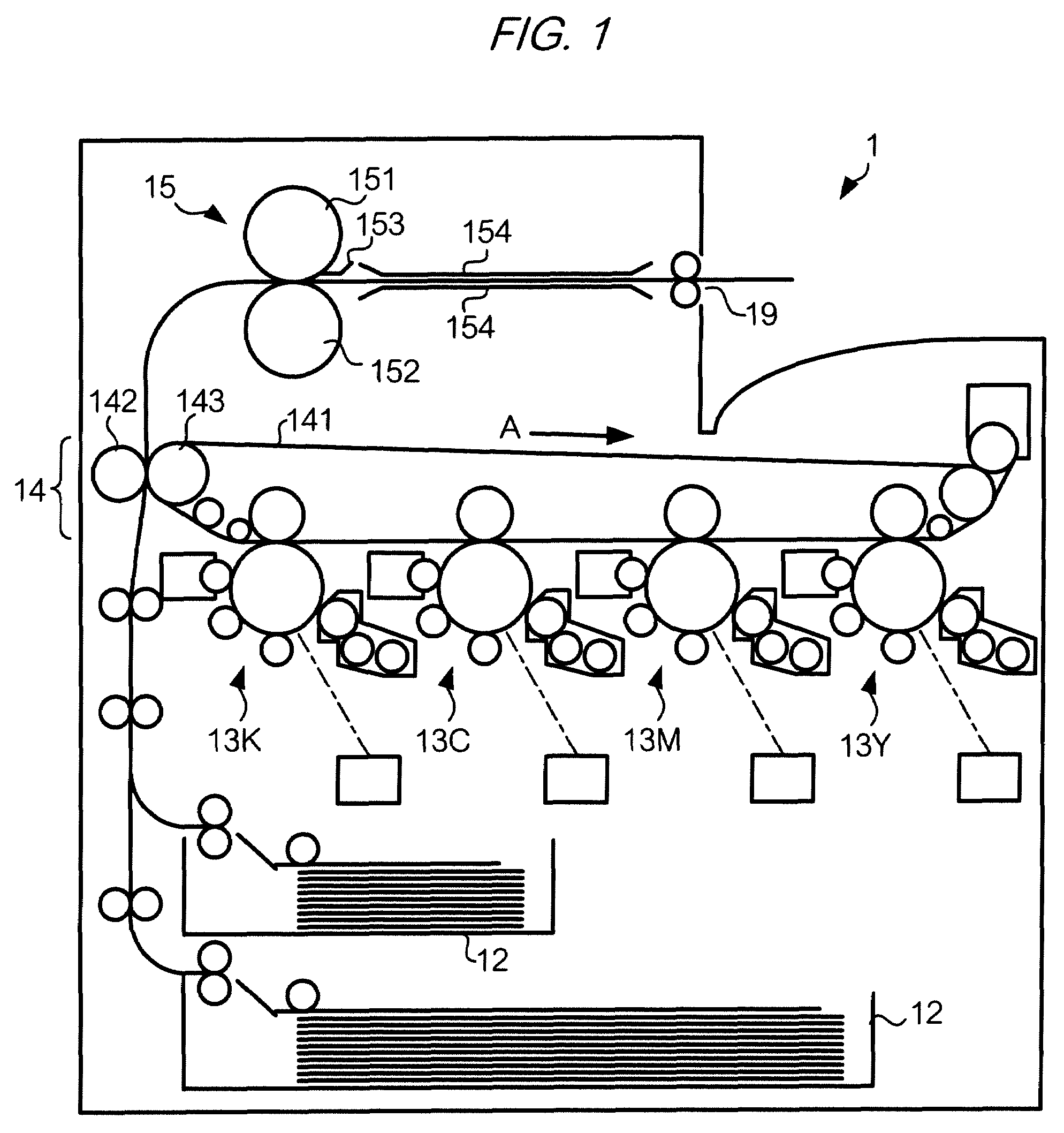
[0044]FIG. 1 shows a structure of an image forming device 1 according to the first exemplary embodiment of the invention.

[0045]As shown in FIG. 1, the image forming device 1 has sheet container units 12, image forming units 13Y, 13M, 13c, and 13K, a transfer unit 14, and a fixing unit 15. These units are controlled by a control unit 1020 which will be described later, and as a whole functions as an image forming unit. Images formed by the image forming unit have, for example, a resolution of 2,400 dpi. Suffixial codes Y, M, C, and K indicate that components denoted at reference symbols added with these suffixial codes refer to components related to yellow, magenta, cyan, and black toners, respectively. Each of the sheet container units 12 contain paper sheets cut into a predetermined size such as A3 or A4 paper sheets contained in sheet container units 12 are picked up one after another by a pickup roller or the like and is conveyed t...

second exemplary embodiment

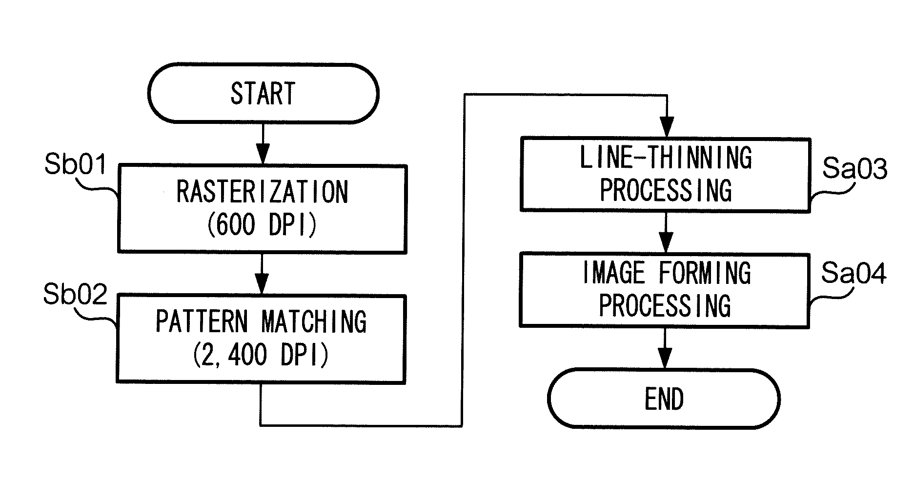
B. Second Exemplary Embodiment

[0070]Next, an image forming device 1 according to the second exemplary embodiment of the invention will be described. Hereinafter, features of the structure which are common to the first exemplary embodiment will be denoted with common reference symbols, and descriptions of those features will be omitted herefrom.

[0071]B-1. Structure

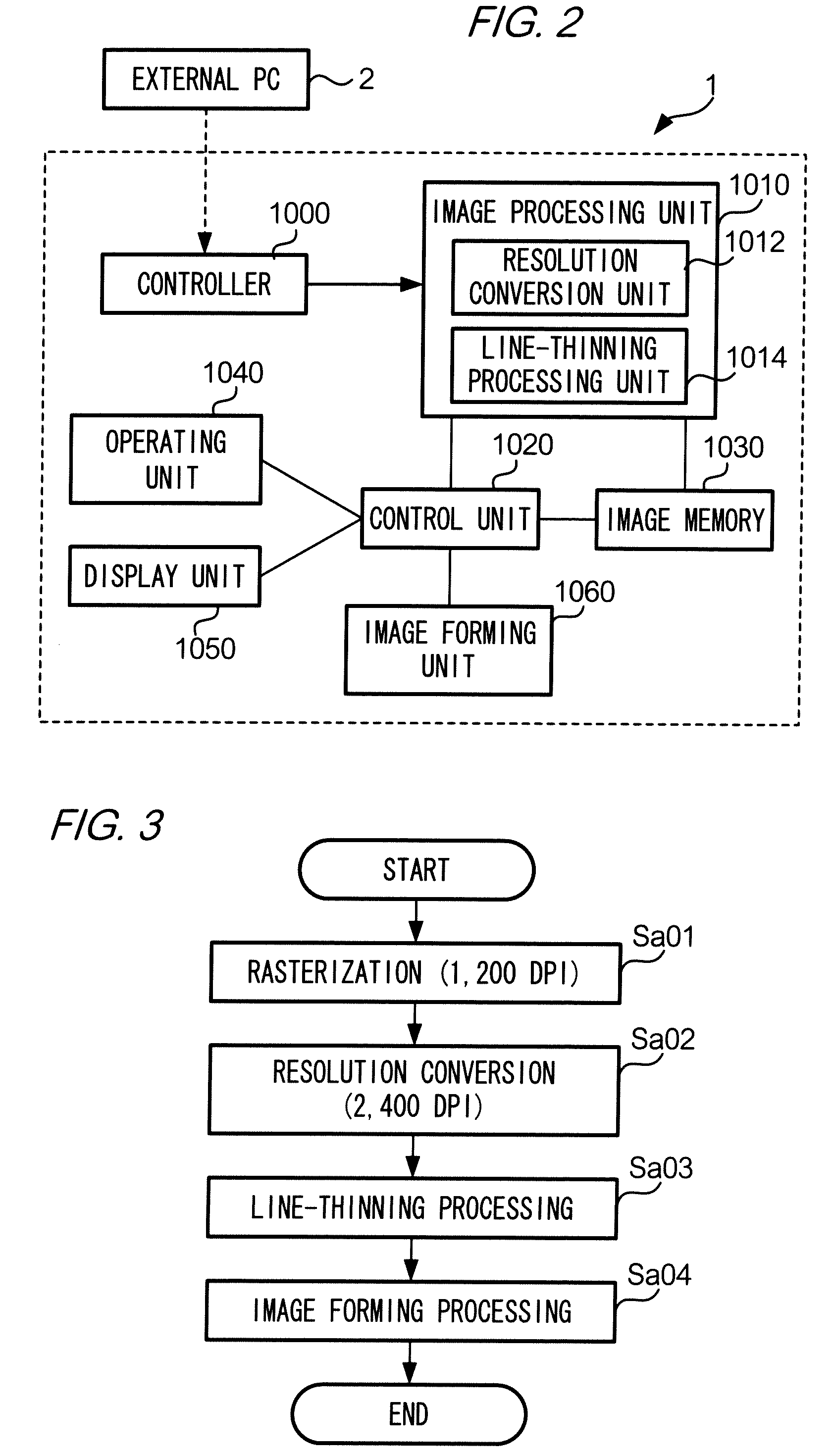
[0072]FIG. 6 is a block diagram showing an electric structure of the image forming device 1 according to the second exemplary embodiment.

[0073]The image forming device 1 according to the second exemplary embodiment has a controller 1001 and an image processing unit 1011 respectively in place of the controller 1000 and the image processing unit 1010 in the first exemplary embodiment. The controller 1001 is basically the same raster image generation unit as the controller 1000 according to the first exemplary embodiment but differs from the controller 1000 in that 600 dpi is the resolution of a raster image which is generated...


PUM


Abstract

An image processing device that outputs a raster image to an image forming unit that forms an image at a first resolution based on the raster image, generates a raster image at a second resolution that is lower than the first resolution; inspects pixels of the generated raster image having the second resolution, and if there is a pixel group including a pixel and pixels surrounding the pixel that has a layout pattern identical to a predetermined layout pattern, replaces the pixel with a predetermined raster image having the first resolution; inspects pixels of the raster image having the first resolution, and if there is a pixel group including a pixel and pixels surrounding the pixel that satisfies a predetermined condition, replaces the pixel with a pixel of a different color; and outputs the raster image having the first resolution subjected to line-thinning to the image forming unit.

Description

CROSS-REFERENCE TO RELATED APPLICATIONS[0001]This application is based on and claims priority under 35 USC 119 from Japanese Patent Application No. 2008-53324 filed on Mar. 4, 2008.BACKGROUND[0002]1. Technical Field[0003]The present invention relates to an image processing device, an image forming device, and an image processing method.[0004]2. Related Art[0005]An image forming device which employs an electrophotographic method sometimes causes a problem of blurring at boundary parts of electrostatic latent images due to characteristics of photosensitive materials. Consequently, lines formed on a surface of a recording material become thick. For example, small letters of a 5-point size or smaller collapse and become illegible. As methods for suppressing such blurred electrostatic latent images, downsizing of a beam aperture used in exposure, and thinning of photosensitive film thickness are commonly known. In addition to these methods, there has been developed a technique for narrow...

Claims


Application Information

Patent Timeline
Patent Type & Authority Patents(United States)
IPC IPC(8): G06K15/02
CPCH04N1/40068G03G15/00
Inventor KUBO, MASAHIKOHARA, TOMOSHI
Owner FUJIFILM BUSINESS INNOVATION CORP
Features
  • R&D
  • Intellectual Property
  • Life Sciences
  • Materials
  • Tech Scout
  • Unparalleled Data Quality
  • Higher Quality Content
  • 60% Fewer Hallucinations
Learn More